
Subscribe to Our Youtube Channel
Related Manuals for Mule Lighting LPS Series

Summary of Contents for Mule Lighting LPS Series
- Page 1 Installation And Operation Instructions For LPS Series Inverter Power Systems LPS-750, LPS-950 AND LPS-1150 True Sinusoidal Output Power 46 Baker Street, Providence, RI 02905 - Phone: (800) 556-7690 - www.mulelighting.com...
- Page 2 READ AND FOLLOW ALL SAFETY INSTRUCTIONS IMPORTANT SAFEGUARDS When using electrical equipment, basic safety precautions should always be followed, includ- ing the following: READ AND FOLLOW ALL SAFETY INSTRUCTIONS: • Do not use outdoors. • Do not let power supply cords touch hot surfaces. •...
-
Page 3: Table Of Contents
Table of Contents Description Page Section 100 System Installation Instructions 101. Specifications ....................... 4 102. Receiving, Moving and Storing Systems and Batteries ........5 102.1 Shipping Damage ....................5 102.2 Temporary Storage of Units and Batteries ............5 103. Installation Requirements ..................5 103.1 Operating Environment .................. -
Page 4: Section 100
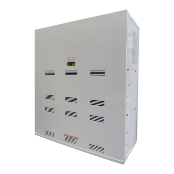
Section 100 System Installation Instructions 101 Specifications Input • Input voltage: Universal 120 or 277Vac. • Input frequency: 60HZ ±2% • Input surge protection: Meets UL 924 Output • Output voltage: Universal 120 or 277Vac, 60HZ. Other voltages available upon request •... -
Page 5: 102. Receiving, Moving And Storing Systems And Batteries
102. Receiving, Moving and Storing Systems and Batteries 102.1 Shipping Damage Inverter system batteries are shipped separately. Carefully inspect all cartons upon receipt for evidence of shipping damage. Notify carrier immediately of leaking or damaged cartons for possible concealed damage. 102.2 Temporary Storage of Units and Batteries For temporary storage of LPS inverter systems and batteries prior to installation, select a clean, cool, dry location with normal ventilation for human habitation and level floors. -
Page 6: 104.2 Mounting Hardware
104.2 Mounting Hardware Mounting hardware is not provided. Care should be taken when selecting mounting hardware to as- sure that it is the proper type for the application and sized to safely support the systems full weight when installed assuring safe and secure attachment of system to wall surface or building structures. For ease of installation, the factory recommends that the head size of mounting screws or bolts be small enough to pass through the keyhole knockouts provided for mounting. -
Page 7: 105.1 Ac Wiring Preparations
105.1 AC Wiring Preparations 1. Remove the system’s front cover. 2. Make sure the LPS inverter system input and output voltages are correct for the particular appli- cation. Remember that the LPS system provides single-phase power only. 3. The input circuit breaker in the input service panel provides the means for disconnecting AC to the LPS inverter system. - Page 8 Switched Load Operation - Single Circuit - Connected fixure(s) can be extremely switched and will illuminate upon loss of utility AC power regardless of external switch position. See Wiring Diagram D. CAUTION: If the Inverter being used has a -4C or -4AO option, then please refer to wiring diagrams E, F or G.
- Page 9 NOTE: Dimming switches S1-1 and S1-2 are designed for independent settings to allow different emergency dimming control voltages for each circuit AVAILABLE AS AN OPTION...
-
Page 10: 106. Battery Information
106. Battery Information Important Safety Precautions The installer must take these precautions: 1) Wear protective clothing, eye-wear, rubber gloves and boots. Batteries contain corrosive acids or caustic alkalis and toxic materials and can rupture or leak if mistreated. Remove rings and metal wristwatches or other metal objects and jewelry. -
Page 11: 106.2 Battery Installation And Connection
106.2 Battery Installation and Connection Battery Placement: The LPS-750, LPS-950, and LPS-1150 models are all provided with (2) parallel battery strings. The 1st string is located in the upper battery compartment, the 2nd string is located in the lower battery compartment. Batteries should be carefully placed in the battery compartments with the positive (+) red terminals facing upwards and outwards. -
Page 12: 106.3 Battery Voltage Check
106.3 Battery Voltage Check Using a digital volt-ohm meter, check for correct nominal battery voltage between DC Input NEG and POS wires. Voltage reading should be ±10% of system’s nominal 48Vdc for LPS-750, 60Vdc for LPS-950 operating voltage or 72Vdc for LPS-1150 operating voltage. 107. -
Page 13: 108. System Start-Up Procedure
108. System Start-Up Procedure IMPORTANT: The LPS inverter system is a sophisticated electronic backup power supply. Care must be taken to follow the steps below in their exact sequence. Failure to do so may result in possible equipment failure. CAUTION: Familiarize yourself with the shut down procedure in Section 200.1 before proceed- ing with the LPS system Start Up. -
Page 14: 110.1 Self-Test/Diagnostic Functions
110.1 Self-Test/Diagnostic Functions The self-diagnostic function is factory preset and performs the following: A) Continuous monitoring of battery, battery charger and connected loads. B) Self-testing and a (30) second discharge with a randomized start (per UL 924, Sec. 30.2), once every (30) days, after normal utility power has been supplied for a minimum of (48) hours. -
Page 15: 200.2 Routine System Maintenance
200.2 Routine System Maintenance The LPS inverter system unit is designed to provide years of trouble-free operation. The unit does re- quire some routine attention to assure peak performance. The Manufacturer recommends a Preven- tative Maintenance check be performed by a qualified service technician at least every six months. The technician must observe important safety precautions while performing the following recommend- ed tasks: •...
Need help?
Do you have a question about the LPS Series and is the answer not in the manual?
Questions and answers