Table of Contents
Advertisement
Quick Links
Advertisement
Table of Contents

Subscribe to Our Youtube Channel
Summary of Contents for Accton Technology CAP2315A
- Page 1 CAP2315A 802.11b/g AP Cradle Installation Guide WA6102-ZZ...
- Page 3 Installation Guide Guide 802.11b/g AP Cradle IEEE 802.11b/g Wireless Access Point, with Cradle Charger for Wi-Fi Phone...
- Page 4 CAP2315A E072006-EK-R01 150xxxxxxxxxxxx...
- Page 5 Compliances Federal Communication Commission Interference Statement This equipment has been tested and found to comply with the limits for a Class B digital device, pursuant to Part 15 of the FCC Rules. These limits are designed to provide reasonable protection against harmful interference in a residential installation. This equipment generates, uses and can radiate radio frequency energy and, if not installed and used in accordance with the instructions, may cause harmful interference to radio communications.
- Page 6 EC Conformance Declaration Marking by the above symbol indicates compliance with the Essential Requirements of the R&TTE Directive of the European Union (1999/5/EC). This equipment meets the following conformance standards: • EN 60950-1 (IEC 60950-1) - Product Safety • EN 300 328 - Technical requirements for 2.4 GHz radio equipment •...
-
Page 7: Table Of Contents
Contents Chapter 1: Introduction Package Checklist Hardware Description Wi-Fi Phone Cradle LED Indicators Ethernet Port Reset Button Power Connector Chapter 2: Hardware Installation Access Point Configuration Appendix A: Troubleshooting Diagnosing Access Point Indicators Appendix B: Cables and Pinouts Twisted-Pair Cable Assignments 10/100BASE-TX Pin Assignments Straight-Through Wiring Crossover Wiring... - Page 8 Contents...
-
Page 9: Chapter 1: Introduction
Chapter 1: Introduction The Cradle Access Point is an IEEE 802.11b/g (Wi-Fi) access point that provides a quality wireless Voice over Internet Protocol (VoIP) service for Wi-Fi phones, and high-speed data communications between a wired LAN and other 802.11b/g mobile devices. -
Page 10: Hardware Description
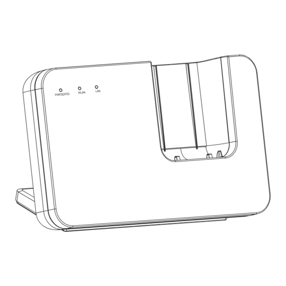
Introduction Hardware Description Front Panel Back Panel Ethernet LAN Reset Power RJ-45 Port Button Socket... -
Page 11: Wi-Fi Phone Cradle
Hardware Description Wi-Fi Phone Cradle The access point accepts a Wi-Fi Phone in its cradle for charging the battery. When the access point is powered on, just place the phone in the cradle and charging starts immediately. LED Indicators The access point includes three status LED indicators, as described in the following figure and table. -
Page 12: Reset Button
Introduction Reset Button The Reset button is used to restart the access point or restore the factory default configuration. If you hold down the button for less than 5 seconds, the access point will perform a hardware reset. If you hold down the button for 5 seconds or more, any configuration changes you may have made are removed, and the factory default configuration is restored to the access point. -
Page 13: Chapter 2: Hardware Installation
Chapter 2: Hardware Installation To install the Cradle Access Point, follow these steps: Select a Site – Choose a proper place for the access point. In general, the best location is at the center of your wireless coverage area, within line of sight of all wireless devices. -
Page 14: Access Point Configuration
Hardware Installation Access Point Configuration The access point can be configured by connecting a PC to its Ethernet port and accessing the web interface. The default IP address of the access point is 192.168.1.20, with login user name “admin” and no default password. For information on configuring the access point, refer to the Management Guide. -
Page 15: Appendix A: Troubleshooting
Appendix A: Troubleshooting Diagnosing Access Point Indicators Troubleshooting Chart Symptom Action PWR/SEATED LED is Off • AC power adapter may be disconnected. Check connections between the access point, the power adapter, and the wall outlet. LAN LED is Off • Verify that the access point and attached device are powered on. •... - Page 16 Troubleshooting...
-
Page 17: Appendix B: Cables And Pinouts
Appendix B: Cables and Pinouts Twisted-Pair Cable Assignments For 10/100BASE-TX connections, a twisted-pair cable must have two pairs of wires. Each wire pair is identified by two different colors. For example, one wire might be green and the other, green with white stripes. Also, an RJ-45 connector must be attached to both ends of the cable. -
Page 18: Straight-Through Wiring
Cables and Pinouts Straight-Through Wiring If the twisted-pair cable is to join two ports and only one of the ports has an internal crossover (MDI-X), the two pairs of wires must be straight-through. EIA/TIA 568B RJ-45 Wiring Standard 10/100BASE-TX Straight-through Cable White/Orange Stripe Orange White/Green Stripe... -
Page 19: Appendix C: Specifications
Appendix C: Specifications Maximum Channels FCC/IC: 1-11 ETSI: 1-13 France: 10-13 MKK: 1-14 Taiwan: 1-11 Maximum Clients 32 per VAP interface Data Rate 802.11g: 6, 9, 11, 12, 18, 24, 36, 48, 54 Mbps per channel 802.11b: 1, 2, 5.5, 11 Mbps per channel Modulation Type 802.11g: CCK, BPSK, QPSK, OFDM 802.11b: CCK, BPSK, QPSK... - Page 20 Specifications Weight 300 g (10.6 oz) LED Indicators PWR/SEATED (Power), LAN (Ethernet Link/Activity), WLAN (Wireless Link/Activity) Network Management Web-browser Temperature Operating: 0 to 50 °C (32 to 122 °F) Storage: -20 to 70 °C (32 to 158 °F) Humidity 15% to 95% (non-condensing) Compliances FCC Part 15B Class B VCCI ClassB...
- Page 22 CAP2315A E072006-EK-R01 150xxxxxxxxxxxx...
Need help?
Do you have a question about the CAP2315A and is the answer not in the manual?
Questions and answers