
Subscribe to Our Youtube Channel
Summary of Contents for Linea Research ASC-48
- Page 1 ASC-48 Processor LNR series processors Linea Research ASC-48 Advanced System Controller User Guide Version 8 (For firmware version 1.460 and above)
-
Page 2: Table Of Contents
FOR CUSTOMERS IN THE USA ......................8 FOR CUSTOMERS IN CANADA ......................9 FOR CUSTOMERS IN SINGAPORE ......................9 Thanks and Unpacking .......................... 10 Unpacking the Linea Research ASC-48 series controller ..............10 INSTALLATION INSTRUCTIONS ......................10 Mechanical Installation ........................10 AC Power Connection ........................11 The User Guide............................ - Page 3 AES3 / Network Inputs ........................25 Automatic Input Selection (Fallover) .................... 25 Gain and Polarity ........................... 25 Delay ............................. 26 High Pass Filter ..........................26 Parametric Equalisation ........................ 26 FIR Shelving EQ..........................26 Parametric Filters .......................... 26 Routing ............................27 Output ...............................
- Page 4 AUTO-IP ............................32 Static-IP ............................32 IP Troubleshooting ........................32 Snapshots ............................32 AUX Port ............................33 Latency delay ............................ 34 Input/Output Latencies ......................... 34 Processing Latencies ........................34 Secure Mode ............................. 35 Overlay Flush ............................. 35 Revert to Factory Settings ......................... 35 Tipi Third Party Interface ........................
-
Page 5: Important Safety Instructions
IMPORTANT SAFETY INSTRUCTIONS The lightning bolt triangle is used to alert the user to the risk of electric shock. The exclamation point triangle is used to alert the user to important operating or maintenance instructions. Read these instructions. Keep these instructions. Heed all warnings. -
Page 6: Consignes De Sécurité Importantes
CONSIGNES DE SÉCURITÉ IMPORTANTES Le triangle de l'éclair est utilisé pour alerter l'utilisateur À risque d'électrocution. Le triangle du point d'exclamation est utilisé pour alerter l'utilisateur sur des importants Instructions d'utilisation ou d'entretien. Lisez ces instructions. Conservez ces instructions. Respectez tous les avertissements. Suivez toutes les instructions. -
Page 7: Compliance
COMPLIANCE FOR CUSTOMERS IN EUROPE This product complies with both the LVD (electrical safety) 2014/35/EU and EMC (electromagnetic compatibility) 2014/30/EU directives issued by the commission of the European Union. Compliance with these directives is demonstrated by conformity with the following European standards: EN60065 8th Edition Electrical safety... -
Page 8: For Customers In The Usa
C have a rating SJ, SJT, SJE or 300/500V H05W-F and be marked VW-1. ATTENTION FCC SUPPLIER'S DECLARATION OF CONFORMITY (SDoC) : We, Linea Research Ltd. of 1 Marquis Business Centre, Royston Road, Baldock, Hertfordshire, SG7 6XL, England, represented in the United States by Allied Professional Technologies, LLC - www.alliedprotech.com... -
Page 9: For Customers In Canada
FOR CUSTOMERS IN CANADA This product complies with CA /CSA C22.2 No.60065-03 for electrical safety. Ce produit est conforme avec CA /CSA C22.2 No.60065-03 pour la sécurité électrique. DECLARATION OF CONFORMITY WITH CANADIAN ICES-003. This Class A digital apparatus complies with Canadian ICES-003. Cet appareil numérique de la classe A est conforme à... -
Page 10: Thanks And Unpacking
All Linea Research products are carefully engineered for world-class performance and reliability. If you would like further information about this or any other Linea Research product, please contact us. We look forward to helping you in the near future. -
Page 11: Ac Power Connection
Where the processor is used in a fixed installation, as long as the bottom unit is supported and there are no gaps between units, it is acceptable to use only the front panel 19” rack mounting points when fitting it in a standard rack enclosure. If the processor is mounted in a mobile rack it is important that either the rear is supported or that it is positioned directly between other supported units. -
Page 12: The User Guide
This user manual gives a progressively more detailed description of the functions of the Linea Research ASC-48 series advanced system controller. A single page quick reference guide is provided for those users who are experienced with this type of equipment and just need to know how to ‘drive’... -
Page 13: Introduction And Key Features
High performance ‘universal mains’ switch mode power supply, designed in-house Drive Modules The ASC-48 processor has a new way of ordering and grouping channels in order to give a more speaker-based approach to controlling, designing and recalling speaker configurations; these are called Drive Modules. - Page 14 Drive Modules may be included in Module Groups, which use the Parameter Overlay feature in the ASC48 to achieve trouble-free Grouping in the System Engineer application. The Presets in the ASC48 are Drive-Module centric, and are used to configure individual Drive Modules rather than the whole device.
- Page 15 FIR Output Processing (available on some models) Each output has a Finite Impulse Response (FIR) filter which may be programmed using a 3 party application for further Equalisation and phase correction. Such FIRs may be designed for Linear Phase response, either for equalisation or from linear phase crossovers.
-
Page 16: Audio Connections
Audio Connections Input Connections For each input channel there is a female XLR input connector. Even channel numbers are for Analogue inputs only. Odd channel numbers are either for Analogue inputs (when in Analogue input mode) or for AES3 input pairs (when in AES3 input mode). The HOT, + or ‘in phase’... -
Page 17: Using Unbalanced Connections
Using unbalanced connections Please note that the use of unbalanced connections is not recommended, however, when connecting the device to an unbalanced audio source, the signal conductor should be connected to XLR pin2. The ‘Cold’ conductor or cable screen should be connected to XLR pin 3 with a short connection made between pin 1 and pin 3. -
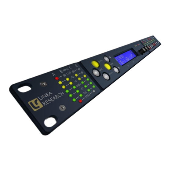
Page 18: Panel Layouts
Panel Layouts Limiter Indicators- The output indicators shows the status of the limiter and output level relative to the limiter threshold. The <SIG> indicator shows signal presence and will illuminate when a signal is present in the output. The second indicator <-6dB> shows that the signal has reached 6dB below the limiter threshold. The third <LIMIT> indicator indicates that the threshold of that output channel has been reached. - Page 19 Tipi protocol. This port is also used for updating the firmware in the unit. Networked Audio Ports- The ASC-48 has the option for networked audio ports; if none are required a blanking plate will be fitted. There are several options for networked audio including Dante™. For a full list please consult your vendor.
-
Page 20: Operation
Operation Starting up the unit The unit will power up as soon as power is applied to the IEC power inlet; there is no power switch. When power is present the unit will go through its start-up cycle - first all the indicators will illuminate then go off, while the screen displays the boot loader information. -
Page 21: Drive Modules
Output 8 component number Drive Modules The ASC-48 uses Drive Modules to represent loudspeaker sub-systems. Drive modules result in a less processor-centric and more speaker-orientated system design. A drive module is defined as the processing provided by one Input DSP, and a number of outputs, which are associated with one- another by means of routing. -
Page 22: Drive Module Presets
Snapshot. Such a Module cannot be saved in a Module Preset. Note: DSP inputs are not the same as physical inputs. The ASC-48 has four audio inputs and four DSP inputs. This is a matrix mixing system where any physical inputs, be they analogue, AES3 or networked audio feeds, can drive any number of DSP inputs. -
Page 23: Navigation And Designing Crossovers
Navigation and Designing Crossovers The ASC-48 has 50 Drive Module preset locations and these can be stored and recalled from the <INPUT> pages, for the channel being viewed. To design a new crossover, press the desired <INPUT> or <OUTPUT> button to enter the pages where the parameters for each of the channels are shown. -
Page 24: Recalling Module Presets
encoder “A” will change the preset number. When the destination preset is reached, pressing the <ENTER> button will enable the name associated with that preset to be changed. Once the name changing is active, the character to be changed will be highlighted and encoder “A” will edit the character. -
Page 25: Input
Input AES3 / Network Inputs In addition to the usual analogue inputs, the ASC can also accept AES3 digital inputs. The same physical XLR sockets are used for both Analogue and AES3 inputs; the function of these being determined by the Type parameters in the Input Type menu. The Input sockets 1 and 3 are used to input pairs of AES3 channels, so setting the input to ‘AES3’... -
Page 26: Delay
-40dB to +20dB. The presence of an active Group Overlay parameter is indicated by the ‘[]’ symbol (See Overlays). This page will also allow users to change the polarity of the selected input from normal to reverse, using encoder “B”. Using encoder “C” will mute the selected channel. Delay The delay page which controls the amount of delay associated with the input channel selected and is adjustable from 0 to 998ms. -
Page 27: Routing
LIR Crossover Filtering Unique to Linea Research, “Linear Impulse Response” (LIR) crossover filtering gives a Linear Phase crossover which has a constant delay regardless of frequency (unlike other types of crossover which... -
Page 28: Parametric Equalisation And All-Pass Filters
Limiters The ASC-48 includes three limiters in the output signal path. Please note that whilst the Limiters in this product offer protection for amplifiers and drivers, they can never protect from all possible... - Page 29 VX Limiter (Unique to Linea Research) This is a peak-detecting RMS-calibrated signal limiter. The VX Mode parameter determines the style of limiter. When Virtual Crossover (VX) mode is off, the limiter is controlled in a conventional manner; the only controls being Threshold and Overshoot.
-
Page 30: Amplifier Gain
To set the limiter up, it is necessary to know the shape of the family of Excursion vs. Frequency curves of the driver for various drive voltage levels. A curve should then be chosen where the slope is high where it passes though the specified X-Max value for the driver. The peak voltage and frequency of this point should then be noted. -
Page 31: Ip Mode
IP Mode The Ethernet IP address may be automatic “Auto” or may be a fixed static value “Static” as determined by the “IP Mode” page of the “UTILITY” menu. WARNING – Do NOT use Static mode unless your IT system specifically requires it. Auto mode should always be used where possible since in this mode, the ASC can always be ‘discovered’... -
Page 32: Auto-Ip
AUTO-IP The device will initially search for a DHCP server when first switched on (during which time its Online Indicator will be flashing). As it can take up to one minute to establish that there is no DHCP server available, this is the time it may take before Auto IP is entered. Please be aware that it can also take some time from a computer being switched on in an isolated network (without a DHCP server), or unplugged from a network with DHCP to time out of DHCP searching, so it will not connect immediately to amplifiers that are already using Auto IP. -
Page 33: Aux Port
existing edits to the parameters in Drive Modules are stored into Drive Module presets before a Snapshot is stored. Also see Overview Of Modules Components and Snapshots AUX Port The AUX has two inputs, X & Y. These allow simple contact closure devices (relays or switches) or external logic signals to change the state of the amplifier as described below. -
Page 34: Latency Delay
Latency delay All Digital Signal Processing, and conversion between different formats of signal – analogue/digital/network etc, necessarily introduce some delay (latency) to the signal path. Of course, we strive to minimise these latencies. Small as they are, it is sometimes useful to know their precise values. -
Page 35: Secure Mode
Example: Input/Output Analogue Input 0.385ms Analogue Output 0.402ms Processing Input HiShelf FIR (Off) LIR Linear Phase crossover (500Hz) 2.38ms VxLim Lim (VX mode on, 1KHz Fsplit) 0.358ms Total 3.525ms Note that the latencies within a Drive Module are equalised among outputs of that Drive Module. That is, padding delay will be automatically added to some outputs such that the total latency is the same in each output of a Drive Module. -
Page 36: Tipi Third Party Interface
Tipi Third Party Interface Whilst the device can be set up and controlled entirely from the front panel, or by using a dedicated control panel in the System Engineer PC application, Tipi provides a powerful yet very simple means of controlling the device using ASCII strings from a very wide range of controller devices. The Tipi protocol uses TCP/IP on the Ethernet interface. -
Page 37: Processing Block Diagram
Processing Block Diagram... -
Page 38: Input Menu Map Utility Menu Map
Input Menu Map Utility Menu Map CH A CH B CH C CH D STATIC IP IP CURR IP MODE FIR/ FIR/ FIR/ FIR/ HOME IP CURR HOME UTIL STEREO HOME HOME HOME STYLE EQ BW HOME SCREEN EQ 2 EQ 2 EQ 2 EQ 2... -
Page 39: Output Menu Map
Output Menu Map …. CH 1 CH 2 CH 8 EQ / EQ / EQ / EQ / HOME EQ 8 EQ 8 EQ 8 EQ 8 HOME EQ 7 EQ 7 EQ 7 EQ 7 HOME EQ 6 EQ 6 EQ 6 EQ 6 HOME... -
Page 40: Eq And Filter Response Graphs
EQ and Filter Response Graphs... - Page 42 All-P ass Filter 1 10 1 10 Frequency , Hz Bandwidths 0.1 to 5 Octav es...
-
Page 43: Technical Specifications
Technical Specifications Input impedance: >10k Ohm balanced Output Imp: <100R imp. balanced Max Input level: +20dBu Max Output level: +18dBu into 600R Sample rate: 96kHz AES3 Input sample rate: 28kHz – 108kHz AES3 Output sample rate: 96kHz Frequency Response: 10Hz - 40kHz (Note 1) Input Dynamic range: >120dBa Typ. -
Page 44: Options
Width: 482mm Depth: 254mm Weight: 2.7kg net Notes: 1. The frequency response reduces to 23kHz on outputs which have FIR enabled. Options There is internal provision for digital audio network option cards to be factory fitted. Currently Linea Research support Dante from Audinate.
Need help?
Do you have a question about the ASC-48 and is the answer not in the manual?
Questions and answers