
Subscribe to Our Youtube Channel
Summary of Contents for Public Safety Equipment KUSTOM SIGNALS ProLaser 4
- Page 1 Kustom Signals, Inc. ProLaser 4 Operator Manual Manual Part Number – 006-0966-00 Rev. 3...
- Page 2 Copyright © 2011-2013, Kustom Signals, Inc. All Rights Reserved. Printed in U.S.A. This publication may not be reproduced, stored in a retrieval system, or transmitted in whole or in part in any form or by any means electronic, mechanical, photocopying, recording, or otherwise without prior written permission of Kustom Signals, Inc.
- Page 3 Important/Notable Information While all of the information in this manual is important, there are some pieces of information where special attention needs to be paid to avoid equipment damage, or specific information needs to be emphasized. This information will be handled as follows: IMPORTANT Indicates an operating procedure, practice, or condition that, if not strictly followed, may cause equipment damage.
- Page 4 This Page Intentionally Left Blank ProLaser 4 Manual Part Number: 006-0966-00 Rev. 3...
-
Page 5: Table Of Contents
ProLaser 4 Table of Contents Chapter Page 1 Product Description ..................1-1 General Description ..................1-1 System Components ..................1-2 Optional Components ................. 1-2 Control Locations ..................1-2 2 System Operation ..................2-1 General Description ..................2-1 ... - Page 6 Connecting the ProLaser 4 to an External Power Source ......2-20 Power Over USB ...................... 2-20 Power Over 12 VDC Car Charger Adapter .............. 2-20 Power Conservation Features ..............2-21 Sleep Mode ......................2-21 Automatic Power Off ....................2-21 ...
- Page 7 6 Regulatory Compliance and Specifications ..........6-1 General Description ..................6-1 Eye Safety ....................6-1 Domestic US Requirements ............... 6-2 Global Regulatory Requirements ..............6-2 FCC Information ..................6-2 Specifications ....................6-3 General Specifications ................6-3 ...
- Page 8 This Page Intentionally Left Blank ProLaser 4 Manual Part Number: 006-0966-00 Rev. 3...
- Page 9 List of Figures Figure Page Figure 1-1. ProLaser 4 Features ..................1-3 Figure 2-1. Rear Display Brightness Screen ................ 2-2 Figure 2-2. Weather Button Location ..................2-3 Figure 2-3. Check Button Location ..................2-4 Figure 2-4. Menu Mode – Displaying the Distance Menu Selection ........2-4 ...
- Page 10 Figure 3-4. Set Max Range Screen ..................3-2 Figure 3-5. Set Direction Screen ..................3-3 Figure 3-6. Set Direction Screen (Set to Approaching) ............3-3 Figure 3-7. DIF-TEST Screen ....................3-4 Figure 3-8. Continuous/Single Selection Screen ..............3-4 ...
-
Page 11: Product Description
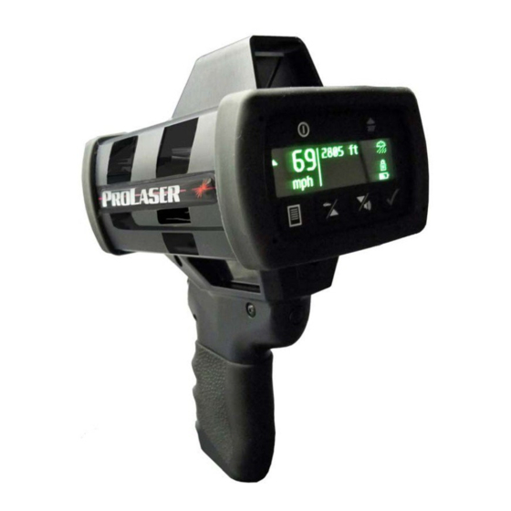
Product Description Chapter 1 Product Description General Description This chapter provides a high-level product description of the ProLaser 4 traffic safety lidar. This product is the latest generation of ProLaser lidar, the most technologically advanced instrument available for speed detection and enforcement. In a compact, handheld package, the ProLaser 4 offers the versatility of direct range and speed measurement. -
Page 12: System Components
Product Description System Components The ProLaser 4 lidar speed detection system consists of the following components: ProLaser 4 ProLaser 4 to PC Cable (Commercial off-the-shelf (COTS) USB cable) 12VDC to 5VDC USB power adapter Eight (8) off-the-shelf, rechargeable NiMH AA batteries and charger ... -
Page 13: Figure 1-1. Prolaser 4 Features
Product Description G. Check button: A multi-function button that runs the unit’s self test when pressed for three (3) seconds in Speed and Range mode or Range mode. The check button is also used to lock and release speed and range displays. On Menu setup screens, the check button is used to select menu options, or act as an enter button. - Page 14 Product Description This Page Intentionally Left Blank ProLaser 4 Manual Part Number: 006-0966-00 Rev. 3...
-
Page 15: System Operation
System Operation Chapter 2 System Operation General Description This chapter provides a detailed explanation of the operating characteristics of the ProLaser 4 speed detection system. IMPORTANT The following guide to operating the ProLaser 4 lidar system is not intended to be a training program. Before operating this unit or any other speed measuring system, Kustom Signals, Inc. -
Page 16: Control Descriptions
System Operation Control Descriptions In Chapter 1 Product Description, the locations of the operating controls and displays were introduced. This chapter will provide detailed descriptions of each control and display. IMPORTANT Use of controls, adjustments or performance of procedures other than those specified is not recommended. Adherence to the instructions contained in this manual insures the device works at peak performance. -
Page 17: Weather Button
System Operation Weather Button The weather button performs two (2) functions: Turn the poor weather filter On and Off Adjust the brightness of the Head-Up Display (HUD) When operating in Speed and Range mode, or in Range mode, a press and hold of the weather button activates poor weather mode. -
Page 18: Check Button
System Operation Check Button The check button is located on the back panel. This button is used to initiate three (3) functions. In Speed and Range mode, or in Range mode, press and hold the check button for three (3) seconds to initiate a self-test. Refer to Accuracy Tests in Chapter 4 Periodic Maintenance for self-test message details. -
Page 19: Speed/Up Button
System Operation Speed/Up Button The speed/up button performs several different functions: To set the unit to either Speed and Range mode, or to Range mode To toggle between Receding only and Both mode To navigate between screens and options in the Menu mode When operating in Speed and Range mode, or Range mode, press and release of the speed/up button to toggle between the two (2) modes. -
Page 20: Figure 2-6. Volume Menu (Setting 2 Shown)
System Operation Lines indicate setting (three (3) lines per increment) Down/volume button Figure 2-6. Volume Menu (Setting 2 Shown) Note: On units sold in Canada, the units will still make some audible noise when the volume is turned Off. Also while operating in Speed and Range mode, or Range mode, the user may press and hold the down/volume button to toggle between Both and Approaching only mode. -
Page 21: Displays And Indicators
System Operation Displays and Indicators Rear Display The primary display of the ProLaser 4 is an OLED located on the back panel of the unit. The display is called the rear display in the remainder of this manual. In addition to speed and range data, the rear display provides setup menus, user alerts, and self-test status. -
Page 22: Display Lock Mode
System Operation Display Lock Mode Display Lock mode is used to lock the display to prevent losing the captured speed information when pursuing the offending vehicle. The ProLaser 4 flashes the Display Lock mode icon on the rear display when the unit is in Display Lock mode. Pressing the check button after releasing the trigger locks the current range and speed readings on the rear display. -
Page 23: Setup
System Operation Setup Two factors should be considered when setting up to make speed or distance measurements with the ProLaser 4. They are (1) the location of the instrument relative to the roadway upon which traffic is moving, and (2) the actual setup in or around the patrol car. In selecting a location for monitoring traffic, be aware that the ProLaser 4 is subject to the cosine effect in the same manner as conventional microwave radar and other laser-based speed measuring systems. -
Page 24: Power-On Sequence
System Operation Power-on Sequence Test Messages Upon power up of the unit or when the check button is pressed and held for three (3) seconds while in Speed and Range mode, or Range mode, the unit will run a self test. When the power button is pressed, the self test will start and one of the following two screens will be displayed, depending on the configuration. -
Page 25: Figure 2-15. Self Test - Timer
System Operation Timer Test: Performs a comparison between the digital CPLD and analog TAC to verify the range and speed determination circuits are operating properly. Figure 2-15. Self Test – TIMER If the TIMER test fails, the message will read TIMER = FAIL and the startup sequence will be aborted. -
Page 26: Mode/Option Selection
System Operation Mode/Option Selection Speed and Range Mode or Range Mode The speed/up button is used to toggle between Speed and Range mode or Range mode. The default mode is Speed and Range mode. Note: It is not necessary to press the check button to confirm (complete mode selection). -
Page 27: Poor Weather Feature
System Operation Poor Weather Feature The Poor Weather feature is used to improve the unit’s sensitivity and performance in adverse weather conditions. Fog, rain, snow and heavy dust can sometimes interfere with the performance of the ProLaser 4. Inability for the unit to lock a speed is a symptom of this problem in the speed mode. -
Page 28: Operating Procedures
System Operation Operating Procedures Speed and Range Mode After completing the range and HUD tests, the ProLaser 4 is now ready to make range and speed measurements. Refer to Chapter 4, Periodic Maintenance, for more information on Accuracy Tests. The ProLaser 4 should be oriented as close to parallel to the traffic flow as the setup location will permit. -
Page 29: Stopwatch Mode
System Operation Since the infrared pulses used by the ProLaser 4 are close to the visible spectrum, the user will find the target objects that best reflect light also provide maximum range from the instrument. If the user experiences trouble getting a range reading to a certain part of a distant object, try a different, flatter surface of the object that may have superior reflective characteristics. -
Page 30: Stpw Distance
System Operation STPW Distance Use the up or down button to move the focus brackets to the desired unit of measure STPW Distance option and press the check button to select the option. Figure 2-24. Enter Distance Screen Use the up or down button to adjust the distance the target vehicle will be traveling during the measurement. -
Page 31: Stpw Measure
System Operation STPW Measure In addition to the STPW Distance mode, the unit enables the user to calculate a distance to be used using the unit’s ranging capability. At the first STPW function screen, press the check button, then use the up or down buttons to move the focus to Measure. Figure 2-27. -
Page 32: Figure 2-31. Difference Between Two Range Measurements Taken Displayed On Screen
System Operation If the second point is where the user is standing, simply press the check button and the ProLaser 4 uses Dist 1 as the total distance. If the user wishes to use a second point that is not where they are standing, the user obtains a second range by aiming the unit at a second reference target at the desired range and pulling the trigger. -
Page 33: Prolaser 4 External Connections
System Operation ProLaser 4 External Connections The ProLaser 4 is equipped with two (2) USB ports. The USB ports can be found on the right side of the handle, at the top, just under the body of the ProLaser 4. The USB ports are hidden behind a flexible rubber cover that hinges at the front (trigger side of handle). -
Page 34: Cordless Operation
System Operation Cordless Operation In its most basic configuration, the ProLaser 4 operates on four (4) rechargeable AA batteries. As the ProLaser 4 is used, the batteries will slowly become depleted. When the battery power becomes too low for operation, the "Replace Batteries" message will appear on the rear display. -
Page 35: Power Conservation Features
System Operation Power Conservation Features The programming of the ProLaser 4 includes two (2) features to help conserve power: Sleep mode Automatic Power Off Sleep Mode The ProLaser 4 will automatically initiate Sleep Mode if there is no activity detected for approximately two (2) minutes. -
Page 36: Setup Of Optional Shoulder Stock
System Operation Setup of Optional Shoulder Stock The ProLaser 4 may be ordered with an optional shoulder stock to provide additional support when targeting vehicles and firing the laser. Use the following information to setup the shoulder stock. Shoulder stock length and rotation adjustment knob Shoulder stock... -
Page 37: Setup Of Optional Tripod
System Operation Setup of Optional Tripod The ProLaser 4 may be ordered with an optional tripod to provide additional support when targeting vehicles and firing the laser. Use the following information to setup the tripod. 1. Locate the tripod to ProLaser 4 mounting bracket, the mounting screw and the tripod mounting block. -
Page 38: Figure 2-38. Attaching The Tripod Mounting Block To The Bracket
System Operation 4. Grab the tripod mounting block and hold it so the threaded end of the captured screw is facing the mounting hole on the bracket. 5. Align the screw with the mounting hole on the left side of the bracket and thread the screw into the hole. -
Page 39: Using The Prolaser 4 Menu System
Using the ProLaser 4 Menu System Chapter 3 Using the ProLaser 4 Menu System General Description This chapter provides a detailed description of the menu system of the ProLaser 4. Menu Mode Menu mode provides access to additional setup and operating features of the ProLaser 4. Enter this mode after the unit has been powered up and completed self test. -
Page 40: Distance
Using the ProLaser 4 Menu System Distance When the user first accesses the menu loop, the Distance menu selection is the first menu selection to appear. Press the check button to access the Distance menu. Figure 3-2. Distance Menu The Distance function is used to set the minimum and maximum ranges at which the target vehicle speeds are displayed. -
Page 41: Set Direction
Using the ProLaser 4 Menu System To manually enter the range, use the up or down buttons to change the maximum range distance setting to the desired distance. 8000 feet (2438 meters) is the default setting. The distance changes in one (1) foot/meter increments. If the user presses the button and holds it down, the display will scroll in 20 foot/meter increments. -
Page 42: Dif-Test
Using the ProLaser 4 Menu System Use the up or down buttons to move the focus brackets to the desired option and press the check button to select the option. Note: The both ( ) setting is the default selection. In approaching mode the approaching symbol ( ) will be displayed on the rear display. -
Page 43: Mph-Km/H
Using the ProLaser 4 Menu System Figure 3-9. Continuous/Single Screen (Continuous Selected) Use the up or down button to move the focus brackets to the desired option and press the check button to select the option. mph-km/h Figure 3-10. mph-km/h Selection Screen Note: On units sold in Canada, the units WILL NOT have the mph –... -
Page 44: Hud Options
Using the ProLaser 4 Menu System HUD Options Figure 3-12. HUD Options Selection Press the check button to access the HUD Options screen. The HUD Options menu is used to turn the range data display in the HUD On or Off, and to set the type of reticle that will be used. Press the check button to access the HUD Options screen. -
Page 45: Hud Reticle
Using the ProLaser 4 Menu System HUD Reticle From the HUD Options menu, the user will access the Reticle settings. The user will press the down arrow button to move the focus brackets to the desired option and press the check button. -
Page 46: Set Time/Date
Using the ProLaser 4 Menu System Press the down button again to display the next most recent event. Continue to press the down button to view the remaining saved events or use the up and down buttons to move between the stored events. Set Time/Date Figure 3-18. -
Page 47: Stopwatch (Stpw)
Using the ProLaser 4 Menu System Stopwatch (STPW) Figure 3-20. Stopwatch (STPW) Menu The STPW menu function is used to set the unit to Stopwatch mode. Stopwatch mode is used to calculate average speed based on the elapsed time taken by a vehicle to travel a predetermined distance. - Page 48 Using the ProLaser 4 Menu System This Page Intentionally Left Blank ProLaser 4 3-10 Manual Part Number: 006-0966-00 Rev. 3...
-
Page 49: Periodic Maintenance
Periodic Maintenance Chapter 4 Periodic Maintenance General Description This chapter provides information for the proper care and maintenance of the ProLaser 4. Cleaning The ProLaser 4 is designed and constructed so that only a minimal amount of normal maintenance is required. Maintenance consists of periodic cleaning of the external optical surfaces. -
Page 50: Accuracy Tests
Periodic Maintenance Accuracy Tests To maintain the accuracy of the ProLaser 4, the agency should perform periodic accuracy tests. The user should always follow the requirements set forth by their agency’s operating procedures to determine the frequency that the accuracy tests be performed. Kustom Signals, Inc. -
Page 51: Laboratory Certification Details
Periodic Maintenance Laboratory Certification Details Kustom Signals, Inc. makes no recommendation or requirement for frequency of calibration for its products. No calibration expiration date for the product is listed on the certificate provided by Kustom Signals, Inc. Calibration intervals normally are fixed by: 1) State law, 2) Judicial precedent or requirement, or 3) Department policy, in that order. -
Page 52: Differential Distance Test (Dif-Test)
Periodic Maintenance Differential Distance Test (DIF-TEST) Prepare two (2) flat targets painted with a flat white paint. Either plywood or particleboard is suitable. Place the targets at two (2) precisely known, integer distances along the same line of sight. Use whole number distances such as 50 or 100 feet (15 or 30 meters), not 50.26 or 75.87. -
Page 53: Figure 4-5. Measure Feature Distance 2 Screen
Periodic Maintenance After a suitable range is obtained, press the check button. The following screen will be displayed: Figure 4-5. Measure Feature Distance 2 Screen Carefully range to the nearest target. After a second suitable range is obtained, it displays in the area adjoining Dist2. - Page 54 Periodic Maintenance This Page Intentionally Left Blank ProLaser 4 Manual Part Number: 006-0966-00 Rev. 3...
-
Page 55: Basic Troubleshooting
Basic Troubleshooting Chapter 5 Basic Troubleshooting General Description This chapter provides instruction for troubleshooting basic system faults. For symptoms not covered in this chapter, please contact Kustom Signals, Inc. Technical Support by calling 1-800-835-0156 or 1-620-431-2700. Basic System Knowledge The person attempting to troubleshoot faults on the ProLaser 4 should have a very good understanding of the operation of the ProLaser 4. -
Page 56: Prolaser 4 Will Not Power On When Using The Usb Power Mode
Basic Troubleshooting ProLaser 4 Will Not Power On When Using the USB Power Mode If a condition exists where the ProLaser 4 system will not power on when using USB power mode, use the following table to diagnose the problem: ProLaser 4 Will Not Power On When Using USB Power Mode Step Action... -
Page 57: Prolaser 4 Does Not Range Or Speed At The Specific Target It Is Pointed At With The Head-Up Display (Hud)
Basic Troubleshooting ProLaser 4 Does Not Range or Speed at the Specific Target it is Pointed At with the Head-Up Display (HUD) If the ProLaser 4 will not range or speed at the specific target that it is pointed at with the HUD, use the following table to diagnose the problem: ProLaser 4 Does Not Range or Speed at the Specific Target it is Pointed At with the HUD Step... - Page 58 Basic Troubleshooting This Page Intentionally Left Blank ProLaser 4 Manual Part Number: 006-0966-00 Rev. 3...
-
Page 59: Regulatory Compliance And Specifications
Regulatory Compliance and Specifications Chapter 6 Regulatory Compliance and Specifications General Description Manufacture and operation of the ProLaser 4 is subject to the regulations of two governmental agencies, the Center for Devices and Radiological Health (or CDRH), and the Federal Communications Commission. -
Page 60: Domestic Us Requirements
Regulatory Compliance and Specifications Domestic US Requirements The ProLaser 4 passes all minimum requirements for Speed-Measuring Device Performance Specifications: LIDAR Module as required by the International Association of Chiefs of Police (IACP) and National Highway Traffic Safety Administration (NHTSA). The ProLaser 4 has been tested and listed on the IACP LIDAR Conforming Product List (CPL). -
Page 61: Specifications
Regulatory Compliance and Specifications Specifications General Specifications Parameter Specification Operating Voltage 4.3 – 7.0 VDC Nominal Voltage (NiMH Batteries) 4.8 VDC Nominal Voltage (Alkaline Batteries) 6.0 VDC Nominal Power Consumption VCC = 6.0 VDC Firing Speed Mode 180 mA Firing Range Mode 175 mA Idle, not firing 155 mA... - Page 62 Regulatory Compliance and Specifications This Page Intentionally Left Blank ProLaser 4 Manual Part Number: 006-0966-00 Rev. 3...
- Page 63 Index Index Accuracy Tests ........4-2 Optional Manual Test ......4-3 Audio Volume ........2-12 Periodic Maintenance ......4-1 Automatic Power Off ......2-21 Poor Weather Feature ......2-13 Basic System Knowledge ....... 5-1 Power Button .......... 2-2 Basic Troubleshooting ......5-1 Power Conservation Features ....
-
Page 64: Index
Index This Page Intentionally Left Blank ProLaser 4 Index-2 Manual Part Number: 006-0966-00 Rev. 3...
Need help?
Do you have a question about the KUSTOM SIGNALS ProLaser 4 and is the answer not in the manual?
Questions and answers