
Related Manuals for ASIX AX58400-TSB


Summary of Contents for ASIX AX58400-TSB
- Page 1 AX58400 GPIO / AIO User Guide Reference Design User Guide AX58400 GPIO / AIO User Guide Revision 1.10 October. 17 , 2023 Copyright (C) 2021-2023 Reserved by ASIX Electronics Corporation...
- Page 2 AX58400 GPIO / AIO User Guide Revision History Reference Design User Guide Revision Date Description 1.00 2021/12/08 Initial release 1.10 2023/10/17 1.Added Evaluation Board License Agreement. Copyright (C) 2021-2023 Reserved by ASIX Electronics Corporation...
-
Page 3: Table Of Contents
6-4 Execution PLC ..................44 7. ADC / DAC Description ....................48 8. Switch ID Description ....................49 9. Firmware Upgrade through EtherCAT FoE ..............58 10. Shortest EtherCAT Cycle Evaluation ................ 63 Copyright (C) 2021-2023 Reserved by ASIX Electronics Corporation... - Page 4 Figure 5 - 18 ..............................31 Figure 5 - 19 ..............................32 Figure 6 - 1 ................................ 33 Figure 6 - 2 ................................ 33 Figure 6 - 3 ................................ 34 Figure 6 - 4 ................................ 34 Copyright (C) 2021-2023 Reserved by ASIX Electronics Corporation...
- Page 5 Figure 10 - 1 ..............................63 Figure 10 - 2 ..............................64 Figure 10 - 3 ..............................64 List of Table Table 5 - 1 ................................24 Table 6 - 1 ................................44 Copyright (C) 2021-2023 Reserved by ASIX Electronics Corporation...
-
Page 6: Introduction
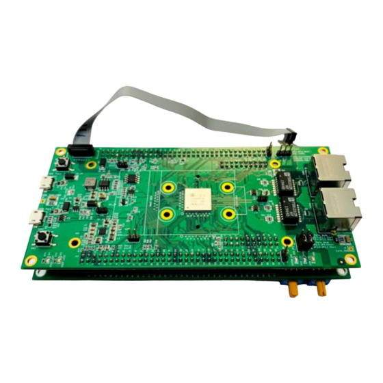
Windows 7 / 10 operation system ⚫ Microsoft Visual Studio 2010 / 2013 ⚫ Beckhoff TwinCAT XAE v3.1.4022.28 or later Figure 2 - 1 Note: You can download the BECKHOFF TwinCAT here or contact ASIX Electronics Corporation. Copyright (C) 2021-2023 Reserved by ASIX Electronics Corporation... - Page 7 ARM KEIL MDK micro-Vision 5 (for development only) Reference Design User Guide Figure 2 - 2 ⚫ STM32CubeIDE 1.4.0 or later Figure 2 - 3 [Hardware] ⚫ AX58400 Test Board (AX58400-TSB) x 1 Figure 2 - 4 Copyright (C) 2021-2023 Reserved by ASIX Electronics Corporation...
- Page 8 AX58400 GPIO / AIO User Guide ⚫ AX58400 ADIO Expansion Board (AX58400-EXB-ADIO) x 1 Reference Design User Guide Figure 2 - 5 Copyright (C) 2021-2023 Reserved by ASIX Electronics Corporation...
-
Page 9: Board Description
3-1 AX58400-TSB AX58400-TSB is an evaluation board for AX58400 IC and has the components list below: ⚫ AX58400 – An ASIX IC that integrated an ESC (EtherCAT Slave Controller) with a dual-core ARM cortex-M7/M4 ESC Port0 – Port0 of the ESC ⚫... -
Page 10: Ax58400-Exb-Adio
ESC Port2 – Port2 of the ESC ⚫ Rotary Dip Switch – A rotary dip switch that can assign a 16-bit digits RS232 Port – The I/O of this RS232 port comes from UART of AX58400-TSB ⚫ Figure 3 - 2... -
Page 11: Basic Operation Of Twincat
4. Basic Operation of TwinCAT Reference Design User Guide Before starting up the AX58400-TSB, you MUST burn the correct content into AX58400 EEPROM first. If there is no the correct content in EEPROM, the MCU will be reset forcibly by ESC. - Page 12 Step 3: Click the “TWINCAT -> Show Realtime Ethernet Compatible Devices…” Figure 4 - 4 ⚫ Step 4: Make sure your network adapter installed BECKHOFF EtherCAT real-time driver If not installed, please click “Install”. Copyright (C) 2021-2023 Reserved by ASIX Electronics Corporation...
- Page 13 “YOUR_BSP_FOLDER\SampleCode\ AX58400_GpioAio\For_TwinCAT\ESI\” Figure 4 - 6 ⚫ Step 6: Copy the file to TwinCAT directory: “C:\TwinCAT\3.1\Config\Io\EtherCAT\” Figure 4 - 7 ⚫ Step 7: Click “TWINCAT -> EtherCAT Devices -> Reload Device Descriptions”. Copyright (C) 2021-2023 Reserved by ASIX Electronics Corporation...
- Page 14 Figure 4 - 8 ⚫ Step 8: Plug USB power and then connect ESC port0 to TwinCAT master port. Figure 4 - 9 ⚫ Step 9: Right-click on “IO / Devices” and select “Scan”. Copyright (C) 2021-2023 Reserved by ASIX Electronics Corporation...
- Page 15 Reference Design User Guide Figure 4 - 10 ⚫ Step 10: Choose main network adapter. Figure 4 - 11 ⚫ Step 11: Click “Yes”. Figure 4 - 12 ⚫ Step 12: Click “Yes”. Copyright (C) 2021-2023 Reserved by ASIX Electronics Corporation...
- Page 16 Step 13: Double click “Device N (EtherCAT)” and you will see the TwinCAT master found the EtherCAT slave Figure 4 - 14 ⚫ Step 14: Select the slave, then right-click and choose “EEPROM Update…” Copyright (C) 2021-2023 Reserved by ASIX Electronics Corporation...
- Page 17 Figure 4 - 16 ⚫ Step 16: Wait for progress bar at lower right corner of the TwinCAT screen. Figure 4 - 17 Step 17: Select “Device N (EtherCAT)”, right-click and choose “Remove”. ⚫ Copyright (C) 2021-2023 Reserved by ASIX Electronics Corporation...
- Page 18 If there is a firmware with Slave Stack Code in AX58400, you should see below screen. The “State” field will show “OP”, that means the device in OP mode. Figure 4 - 21 Note: Please refer to Chapter 5 for firmware download. Copyright (C) 2021-2023 Reserved by ASIX Electronics Corporation...
-
Page 19: Download Firmware To Ax58400
However, please install the ST-Link Driver first to do the following method. You can download the driver through the link ST-LINK DRIVER or install the driver from AX58400 BPS\Driver folder directly. Figure 5 - 1 Copyright (C) 2021-2023 Reserved by ASIX Electronics Corporation... -
Page 20: Stm32Cubeprogrammer Tool Method
Run the STM32CubeProgrammer tool and you will see the picture as below. Figure 5 - 2 And let “STLink-V3Mini Port” to connect your host as following: Figure 5 - 3 Copyright (C) 2021-2023 Reserved by ASIX Electronics Corporation... - Page 21 2. Click the button “Browser” to select the firmware file, for example, “AX58400_GpioAio_CM7.bin” from the directory “YOUR_BSP_FOLDER\SampleCode\ AX58400_GpioAio\Binary\. 3. Specified the start address where the firmware will be programmed, 0x08020000 for example. 4. Click the button “Start Programming” to download the firmware into AX58400. Copyright (C) 2021-2023 Reserved by ASIX Electronics Corporation...
- Page 22 GPIO / AIO User Guide Reference Design User Guide Figure 5 - 6 Note: If you want to check out the firmware status for judge if the download is success, please refer to Chapter 5.4. Copyright (C) 2021-2023 Reserved by ASIX Electronics Corporation...
-
Page 23: Arm Keil Mdk Method
If you had done the actions above, you can keep following below description. Connect “STLink-V3Mini” to your host: Figure 5 - 7 Open the KEIL project by double-click the project file “AX58400_GpioAio.uvprojx” in the directory “YOUR_BSP_FOLDER\SampleCode\ AX58400_GpioAio \MDK-ARM”: Copyright (C) 2021-2023 Reserved by ASIX Electronics Corporation... - Page 24 Print current digit (8bit) of “Rotary_Dip_Switch” of EXB-ADIO SWITCH_ID_DEBUG ADC _NEXT_TIMEOUT Duration for conversion of software for ADC DAC _NEXT_TIMEOUT Conversion duration of software for DAC Duration for print digit of “Rotary_Dip_Switch” SWITCH_DBG_NEXT_TIMEOUT Table 5 - 1 Copyright (C) 2021-2023 Reserved by ASIX Electronics Corporation...
-
Page 25: Stm32Cube Method
At any time during the development, the user can return to the initialization and configuration of the peripherals or middleware and regenerate the initialization code with no impact on the user code. Copyright (C) 2021-2023 Reserved by ASIX Electronics Corporation... - Page 26 The detail information refers the link above. In the directory of BSP, the user can find the file as below. Using the left-button of mouse and double-clicks on the icon, the STM32CubeIDE willl be opened and shows as below. Copyright (C) 2021-2023 Reserved by ASIX Electronics Corporation...
- Page 27 Figure 5 - 12 We assume it is ready in your environment and includes the source files through BECKHOFF SSC Tool. If you already prepared above-mentioned items, you can keep following below description. Copyright (C) 2021-2023 Reserved by ASIX Electronics Corporation...
- Page 28 (2) Main program file of AX58400_GpioAio reference design (3) The button named “Build Project” for build all target files (4) The button named “Run” to download firmware into AX58400 and start to run Copyright (C) 2021-2023 Reserved by ASIX Electronics Corporation...
- Page 29 AX58400 GPIO / AIO User Guide Reference Design User Guide Figure 5 - 14 Figure 5 - 15 Copyright (C) 2021-2023 Reserved by ASIX Electronics Corporation...
-
Page 30: Check Firmware Status
It is helpful using console to check the firmware status. User just needs to connect the “COM” port to the host and open the COM port. Connect the “COM Port” to your host: Copyright (C) 2021-2023 Reserved by ASIX Electronics Corporation... - Page 31 Figure 5 - 18 Open the COM port. If no characters appear in COM port, you can press “Reset” button to confirm again. Below screen shows the firmware of the EtherCAT Slave Stack working successfully. Copyright (C) 2021-2023 Reserved by ASIX Electronics Corporation...
- Page 32 AX58400 GPIO / AIO User Guide Reference Design User Guide Figure 5 - 19 Copyright (C) 2021-2023 Reserved by ASIX Electronics Corporation...
-
Page 33: Plc Application
Please refer to below steps: ⚫ Step 1: Right-click on “PLC” entry and select “Add Existing Item…” Figure 6 - 2 ⚫ Step 2: Select the file “AX58400GpioAio_vX_X_X.tpzip” in your BSP directory “YOUR_BSP_FOLDER\SampleCode\AX58400_GpioAio\For_TwinCAT\”. Copyright (C) 2021-2023 Reserved by ASIX Electronics Corporation... - Page 34 Figure 6 - 3 And you will see below screen, the demo application be inserted into PLC entry. Figure 6 - 4 ⚫ Step 3: Right-click on “SYSTEM -> Tasks” and select “Add New Item…” Copyright (C) 2021-2023 Reserved by ASIX Electronics Corporation...
- Page 35 Reference Design User Guide Figure 6 - 5 ⚫ Step 4: Type “Plc Task” on “Name” field and click “OK”. Figure 6 - 6 ⚫ Step 5: Click “AX58400GpioAio Project -> Add -> Referenced Task…” Copyright (C) 2021-2023 Reserved by ASIX Electronics Corporation...
- Page 36 AX58400 GPIO / AIO User Guide Reference Design User Guide Figure 6 - 7 ⚫ Step 6: Select the “Plc Task” and click “Open”. Copyright (C) 2021-2023 Reserved by ASIX Electronics Corporation...
- Page 37 ⚫ Step 7: Right-click on “AX58400GpioAio Project -> Plc_Task -> Add” and select “Existing Item…” Figure 6 - 9 ⚫ Step 8: Select the “AX58400GpioAio -> POUs -> MAIN” and click “OK”. Copyright (C) 2021-2023 Reserved by ASIX Electronics Corporation...
- Page 38 AX58400 GPIO / AIO User Guide Reference Design User Guide Figure 6 - 10 Step 3: Right-click on “AX58400GpioAio Project” and select “Build”. ⚫ Copyright (C) 2021-2023 Reserved by ASIX Electronics Corporation...
- Page 39 Yellow color indicates the software variables are used for read PD (Process Data) input value from slave. Red color indicates the software variables are used for write PD (Process Data) output value to slave. Figure 6 - 12 Copyright (C) 2021-2023 Reserved by ASIX Electronics Corporation...
-
Page 40: Pd Link
We illustrate procedure of PD link here. If you want to create a PD link, please follow below procedure: ⚫ Step 1: Right-click on specific software variable and select “Change Link…” Figure 6 - 13 ⚫ Step 2: Select specific PD and click “OK” Copyright (C) 2021-2023 Reserved by ASIX Electronics Corporation... - Page 41 AX58400 GPIO / AIO User Guide Reference Design User Guide Figure 6 - 14 Then you will see the black arrow icon appears. Copyright (C) 2021-2023 Reserved by ASIX Electronics Corporation...
- Page 42 If you want to check out linked PD, just right click on the software variable and select “Goto Link Variable”. If you want to check out linked software variable while mouse focus on the PD, just do the same step above. Copyright (C) 2021-2023 Reserved by ASIX Electronics Corporation...
- Page 43 GPIO / AIO User Guide Reference Design User Guide Figure 6 - 16 If you want to clear the link, just right click on the software or PD and select “Clear Link(s)”. Figure 6 - 17 Copyright (C) 2021-2023 Reserved by ASIX Electronics Corporation...
-
Page 44: Link Reference
Note: You MUST setup PD link so that TwinCAT master can let the slave enter to OP mode. Figure 6 - 18 Please follow the steps for execute of PLC application: ⚫ Step 1: Confirm the AX58400 in “OP” mode Copyright (C) 2021-2023 Reserved by ASIX Electronics Corporation... - Page 45 Reference Design User Guide Figure 6 - 19 Step 2: Click “Login” Figure 6 - 20 ⚫ Step 3: Click “Yes” Figure 6 - 21 ⚫ Step 4: Click ”Start” icon Figure 6 - 22 Copyright (C) 2021-2023 Reserved by ASIX Electronics Corporation...
- Page 46 Highlight 5: Input hex value here for control analog output to “DAC” voltage of EXB-ADIO board. Note: Both the ADC and DAC of AX58400 are 12bit accuracy although they declare 16bit in PD. Copyright (C) 2021-2023 Reserved by ASIX Electronics Corporation...
- Page 47 AX58400 GPIO / AIO User Guide Reference Design User Guide Figure 6 - 24 Copyright (C) 2021-2023 Reserved by ASIX Electronics Corporation...
-
Page 48: Adc / Dac Description
Assume measured VCC = 3.27v, the voltage of ADC / DAC will be: ◼ Analog Input Voltage = 3.16 x (ADC_HEX_VALUE_IN_PLC_GUI / 0xFFFF) ◼ Analog Output Voltage = 3.16 x (DAC_HEX_VALUE_IN_PLC_GUI / 0xFFFF) Copyright (C) 2021-2023 Reserved by ASIX Electronics Corporation... -
Page 49: Switch Id Description
ASIX’s configuration file. Figure 8 - 1 This setting will make TwinCAT master enable the identification function for the slave. Select the slave, right-click and select “Advanced Settings…”. Figure 8 - 2 Copyright (C) 2021-2023 Reserved by ASIX Electronics Corporation... - Page 50 Figure 8 - 3 Confirm current identification ADO (Address Offset) is “(ADO 0x0134)”. Don’t forget to assign the value in decimal. The value “55” is just an example here. Figure 8 - 4 Copyright (C) 2021-2023 Reserved by ASIX Electronics Corporation...
- Page 51 The digit format “Rotary Dip Switch” is hex so that we should set it to “0x37”. Reference Design User Guide Figure 8 - 5 Reboot the AX58400-TSB board by click “Reset” button. Figure 8 - 6 Re-activate the TwinCAT master.
- Page 52 But it needs to turn on second address function in ESC register. However, we arrange command for observe this behavior first. You can append an EtherCAT command to TwinCAT master for confirm the second address. Click “Device N (EtherCAT) -> Append EtherCAT Cmd”. Copyright (C) 2021-2023 Reserved by ASIX Electronics Corporation...
- Page 53 AX58400 GPIO / AIO User Guide Reference Design User Guide Figure 8 - 9 Please assign “Command” and “Type”. I demonstrate “FPRD” and “UINT” in this example. Figure 8 - 10 Copyright (C) 2021-2023 Reserved by ASIX Electronics Corporation...
- Page 54 Double-click “Cmd 1” and setup “Slave Address” and “Address Offset”. I setup slave address = 0x37 and address offset = 0x12 in this example. Reference Design User Guide Figure 8 - 11 Re-activate the TwinCAT master again. Copyright (C) 2021-2023 Reserved by ASIX Electronics Corporation...
- Page 55 If you expect that the slave can also use this Switch ID value as second slave address. You just turn on “Seconds address” bit (bit8 = 1) in ESC register 0x0102 (don’t forget click “Write” button). Copyright (C) 2021-2023 Reserved by ASIX Electronics Corporation...
- Page 56 Click “Device N (EtherCAT) -> Cmd 1 -> DATA”, you will see the command get the value of ESC register 0x0012 back successfully. It is correct, the “0x0037” in UINT data type. Copyright (C) 2021-2023 Reserved by ASIX Electronics Corporation...
- Page 57 AX58400 GPIO / AIO User Guide Reference Design User Guide Figure 8 - 15 Copyright (C) 2021-2023 Reserved by ASIX Electronics Corporation...
-
Page 58: Firmware Upgrade Through Ethercat Foe
Application area and then erased the first sector of FoE Backup Image area, finally jump to the Application area and start the latest firmware. Restart the AX58400 device and connect it to TwinCAT master. If everything is OK, you will see the AX58400 in OP mode. Copyright (C) 2021-2023 Reserved by ASIX Electronics Corporation... - Page 59 Right-click the AX58400, click the “Firmware Upgrade” and select the firmware file from BSP directory “YOUR_BSP_FOLDER\SampleCode\AX58400_GpioAio\MDK-ARM\Foe\AX58400_GpioAio.efw” or “YOUR_BSP_FOLDER\SampleCode\AX58400_GpioAio\CM7\Foe\AX58400_GpioAio.efw” A dialog will pop up and just click “OK” button. Figure 9- 3 Check out the progress bar and wait for it finish. Copyright (C) 2021-2023 Reserved by ASIX Electronics Corporation...
- Page 60 USE_BOOTLDR macro must be specified in C/C++ configuration. The checkbox of Use Memory Layout from Target Dialog in Linker configuration must be checked as the figure below. Copyright (C) 2021-2023 Reserved by ASIX Electronics Corporation...
- Page 61 For STM32CubeIDE, the figures show below. Following the steps to add a new macro, USE_BOOTLDR. 1. Select the target project, AX58400_GpioAio_CM7, and 2. Right click of mouse to select tab, Properties. a. Press Add b. Enter the macro, USE_BOOTLDR c. Press OK Copyright (C) 2021-2023 Reserved by ASIX Electronics Corporation...
- Page 62 ORIGIN, from 0x08000000 to 0x08020000. The image will start up from the address 0x08020000 and the binary of image must be programmed into the starting address 0x08020000. After the steps done above, both of cases, MDK-ARM and STM32CubeIDE, the file system_stm32h7xx_dualcore_boot_cm4_cm7.c must be modified as following. Copyright (C) 2021-2023 Reserved by ASIX Electronics Corporation...
-
Page 63: Shortest Ethercat Cycle Evaluation
This reference design allocates TX-PDO (3 bytes) and RX-PDO (3 bytes) totally. Please refer to below figures. Figure 10 - 1 Under this condition, the “Lost Frames” and “Tx/Rx Errors” does not count. Copyright (C) 2021-2023 Reserved by ASIX Electronics Corporation... - Page 64 Reference Design User Guide Figure 10 - 2 The slave stack also does not indicate any errors in SM output parameter / SM input parameter objects of CoE-Online table. Figure 10 - 3 Copyright (C) 2021-2023 Reserved by ASIX Electronics Corporation...
- Page 65 (4) You may not alter, modify, copy or otherwise misappropriate any ASIX electronic product, whether in whole or in part. ASIX Electronics shall not be liable for any loss incurred by you or a third party as a result of altering, modifying, copying or otherwise misappropriating ASIX Electronics products.
- Page 66 No part of this document may be reproduced or transmitted in any form or by any means, electronic or mechanical, including photocopying and recording, for any purpose, without the express written permission of ASIX. ASIX may make changes to the product specifications and descriptions in this document at any time, without notice.
- Page 67 AX58400 GPIO / AIO User Guide Reference Design User Guide 4F, No.8, Hsin Ann RD., Hsinchu Science Park, Hsinchu, Taiwan, R.O.C. TEL: +886-3-5799500 FAX: +886-3-5799558 Email: support@asix.com.tw Web: https://www.asix.com.tw Copyright (C) 2021-2023 Reserved by ASIX Electronics Corporation...
Need help?
Do you have a question about the AX58400-TSB and is the answer not in the manual?
Questions and answers