
Summary of Contents for Automatic Technology DCB-05V2
- Page 1 Dual Gate Controller 24 Volt Gate Control System DCB-05V2 Doc # 160020_06 Released 07/06/22...
-
Page 2: Table Of Contents
Automatic Technology Australia Pty Ltd hereby further expressly excludes all or any liability for any injury, damage, cost, expense or claim whatsoever suffered by any person as a result whether directly or indirectly from failure to install the Automatic Technology Australia Pty Ltd Garage Door Opener in accordance with these installation instructions. -
Page 3: Important Safety Instructions
The safety alert symbols below indicate a personal safety or property damage instruction exists. READ THESE INSTRUCTIONS CAREFULLY. This DCB-05V2 Gate Opener is designed and tested to offer safe service provided it is installed and operated in strict accordance with the following safety rules. Failure to comply with the following instructions may result in death, serious personal injury or property damage. -
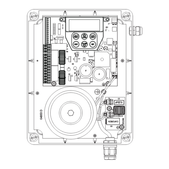
Page 4: Control Board Layout
COM terminal for Terminals Console display (LCD) 19,20,22 &23. SWP N/O input terminal MOTOR 1 close limit switch Antenna connector input terminal PED N/O input terminal MOTOR 1 open limit switch input terminal MOTOR 1 terminal DCB-05V2 Gate Controller Owner Installation Instructions... -
Page 5: Set Up Requirements
SCREW “P” M3.5 X 13 PTX-6 TRANSMITTER RESISTOR 5K6 3.2 Choosing your Set up The DCB-05V2 can be set up in various ways and therefore may require additional items. Common Set ups are as follows; Set Up Items Required Automated Set Up... -
Page 6: Wiring Diagrams - Single Gates
CAUTION: Cables which have a green/yellow coloured insulation are for earthing purposes only. Never use these cables for any other purpose. 5.1 Wiring motors and limit switches DCB-05V2 can be connected to the single gate drive units in one of several ways. Wiring... -
Page 7: Wiring Diagrams - Dual Gates
CAUTION: Cables which have a green/yellow coloured insulation are for earthing purposes only. Never use these cables for any other purpose. 6.1 Wiring motors and limit switches DCB-05V2 can be connected to the dual gate drive units in one of several ways. Wiring... -
Page 8: Dual Neoslider Kit
6.3 Dual NeoSlider Kit (Fig. 6.4) This section illustrates how to wire two NeoSlider slave openers into a DCB-05V2. NOTE: When setting limits, if both openers are travelling in different directions (i.e one is opening and the other is closing), then do the following: a. -
Page 9: Programming The Dcb-05V2
7.2). After a short delay the MAIN and firmware version EXIT SCREEN will be displayed. b. If this is the first time the DCB-05V2 has been used, the MAIN (Fig. 7.3). SCREEN should indicate that the limits are not set If the display shows that some input is active then rectify the situation before proceeding. -
Page 10: Setting Limits
Otherwise press EXIT and check the wiring (Fig. 8.3). 8.2 Adjusting Close Limit(s) a. DCB-05V2 will prompt one at a time for the motor(s) to be driven to Adjusting The CLOSE LIMIT the desired close limit and for the limit switches to be adjusted so that the motor stops at the desired position. -
Page 11: Code A Transmitter For Limit Setting
8. Setting Limits: Via Transmitter The DCB-05V2 has the alternate ability to set travel limits using a transmitter, allowing free movement around the gate to better assess Button 1 the desired limit positions. In order to use a transmitter, it must first... -
Page 12: Safety Obstruction Force Test
(depending on the position of the gate(s) and the power up in Section 9.2 condition). b. A single beep will be heard once the process is complete. c. Test the force again as per “Safety Obstruction Force Test” (Section 9.1 and 9.2). DCB-05V2 Gate Controller Owner Installation Instructions... -
Page 13: Coding Transmitter
10. Coding Transmitter DCB-05V2 can store up to thirty (30) transmitters in its memory. IMPORTANT NOTE: Only TrioCode Each transmitter can be allocated an alpha-numeric ID label up to Technology Transmitters are compatible with eleven (11) characters in length and each button can be assigned this product. -
Page 14: Setting Pedestrian Position
12. Setting Pedestrian Position DCB-05V2 can be instructed, via its pedestrian control feature, to partly open and provide pedestrian access but prevent vehicle access. This is achieved by partly opening the motor 1 gate leaf. If dual motors are used, motor 2’s gate leaf is held closed. -
Page 15: Auto-Close Mode
As with the other Safety Beam modes, the STP input will abort countdown and the OPN and SWP inputs will restart the countdown if the gate is OPEN. Owner Installation Instructions DCB-05V2 Gate Controller... -
Page 16: Accessories Installation
Use a screwdriver to remove the screw on the back of the transmitter casing. c. Use the screwdriver to pry open the plastic to expose WARNING! Chemical Burn Hazard. Keep DCB-05V2 Gate Controller Owner Installation Instructions circuit board. batteries away from children... -
Page 17: Battery Disposal
When batteries reach the end of their usual life in accordance with Australian Battery Recycling Initiative please follow the next simple steps for protecting the environment. Refer to the Automatic Technology website for information on where to recycle batteries in Australia. -
Page 18: Troubleshooting
Safety Beam is obstructed. Remove obstruction from path of Safety Beams. Gate obstructed when closing. Remove obstruction. Auto-Close time not set. Set Auto-Close times (Section 13.3). Auto-Close mode not set Set Auto-Close mode. (Section 13.2) DCB-05V2 Gate Controller Owner Installation Instructions... -
Page 19: Appendix
CLOSE LOCK TIME Set the time the lock is activated for on close Hold 14.1 cycles PRE-OPEN LOCK TIME Time the lock is activated for prior to 25.5 14.1 opening PRE-CLOSE LOCK TIME Time the lock is activated for prior to 25.5 14.1 closing Owner Installation Instructions DCB-05V2 Gate Controller... - Page 20 M2 NORMAL CLOSE TIME 60.0 6.12 Normal close time for motor 2 M1 CLOSE DELAY 25.5 6.13 Close Delay for Motor 1 MAX OVERRUN TIME 6.14 Extra time allowed for cycle to complete (beyond normal cycle time) DCB-05V2 Gate Controller Owner Installation Instructions...
- Page 21 Selects function of OUTPUT2 LIGHT DRIVE LIGHT DRIVE 3 WIRE SB 0V 3 WIRE SB 0V NOT USED NOT USED FAULT AUTO RESET 7.16 Appendix C SBFEC MODE AVAILABLE AVAILABLE AVAILABLE 7.17 Appendix C Owner Installation Instructions DCB-05V2 Gate Controller DISABLED DISABLED...
-
Page 22: B - Viewing And Editing Parameters
Default?” SCREEN. of loading screen, default value giving option of Exits back to Saves new loading Decrease View Mode value and default value with no exits back value changes made to View DCB-05V2 Gate Controller Owner Installation Instructions Mode... -
Page 23: C - Control Board Adjustments
Vacation mode can be turned on or off using this parameter. Motor speed DCB-05V2 supports a Vacation mode where remote control The motor settings adjust various aspects of the gate travel. access is disabled. The mode is activated by pressing a... -
Page 24: D- Diagnostic Tools
ID or serial numbers EXIT are to be displayed. DCB-05V2 will then beep each time a transmission is received. If the transmitter button is stored in the DCB-05V2’s memory and has a function assigned to it, a second screen will be displayed that shows the transmitter details along with the button pressed (Fig. - Page 25 Appendix D- Diagnostic Tools Menu 8.3 Display History DCB-05V2 keeps a record of the last 64 events that have taken place. The events include the type of 124 ID B B SMITH drive cycles executed, obstruction detection, various OSC PED LGT>VAC faults, power failures etc.
-
Page 26: E - Memory Tools
Press SET to Confirm or NEXT/PREV to move to the next field. Fig F.3 PRESS PREV NEXT This is useful when managing transmitters using a scheme which ties the store location to the transmitter’s owner. PRESS EXIT DCB-05V2 Gate Controller Owner Installation Instructions... -
Page 27: G- Transmitter Managment
NEXT EXIT Appendix G- Transmitter Managment Transmitter Listing Facility DCB-05V2 provides a transmitter listing facility which enables the user Press Tx’er to find a transmitter location within memory. Once located a stored Button! LIST> transmitter can be replaced, deleted, edited, copied or, if the location is empty, a new transmitter can be coded. -
Page 28: H- Amp Travel (2 Wires Setup)
NEXT is displayed then press SET to continue otherwise press EXIT and check the wiring. g. DCB-05V2 will now automatically detect if one or two motor are EXIT PRESS connected. If the correct number is displayed then press SET to (Fig. - Page 29 H- AMP Travel (2 Wires Setup) Test and Adjust Stop Detection Confirming Detected Motor Wiring For this type of installation the DCB-05V2 detects the travel limits by sensing a motor current trip when the mechanical stop is reached. M1&2 Detected...
-
Page 30: I - Time Travel 2 Wire Setup
Enter the number or motors by using the UP or DOWN key to select the correct number and then press SET. EXIT PRESS Selecting Setup Method a. DCB-05V2 will now prompt for the setup procedure to be selected. (Fig. I.2); There are 2 methods Selecting install method i. - Page 31 Owner Installation Instructions DCB-05V2 Gate Controller...
- Page 32 © June 2015 Automatic Technology (Australia) Automatic Technololgy (Australia) Pty Ltd Pty Ltd. All rights reserved. TrioCode™128 ABN 11 007 125 368 is a trademark of Automatic Technology 6-8 Fiveways Boulevard Keysborough, Victoria, 3173, Australia (Australia) Pty Ltd. No part of this document P 1300 133 944 may be reproduced without prior permission.
Need help?
Do you have a question about the DCB-05V2 and is the answer not in the manual?
Questions and answers