Table of Contents
Advertisement
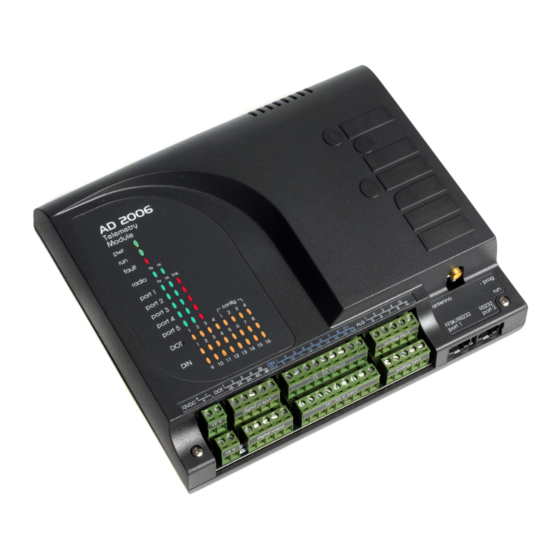
AD2006
TELEMETRY MODULE
QUICKSTART MANUAL
AD2006 (Revision 4)
Note: Before applying power, ensure that the power supply and all wiring is correctly connected. The product
warranty does not cover installation error.
©Miri Technologies -
www.miri.com.au
- Telephone: (+61 8) 9409 8998, Fax: (+61 8) 9409 9229
30 Buckingham Drive. Wangara, WA 6065 Australia
Advertisement
Table of Contents

Related Manuals for MIRI AD2006

Summary of Contents for MIRI AD2006
- Page 1 AD2006 TELEMETRY MODULE QUICKSTART MANUAL AD2006 (Revision 4) Note: Before applying power, ensure that the power supply and all wiring is correctly connected. The product warranty does not cover installation error. ©Miri Technologies - www.miri.com.au - Telephone: (+61 8) 9409 8998, Fax: (+61 8) 9409 9229...
-
Page 2: Table Of Contents
Vertically Polarised 450 – 470 MHz Antennas ..................8 Wiring & Mounting ..........................9 Wiring ............................9 Mounting ............................9 MIRI AD2006 Quickstart Manual_v1.16.docx ©Miri Technologies - www.miri.com.au - Telephone: (+61 8) 9409 8998, Fax: (+61 8) 9409 9229 30 Buckingham Drive. Wangara, WA 6065 Australia... -
Page 3: Scope Of This Manual
For programming information please refer to the MiriMap 2000+ Software on-line help. 2. Ordering Information There are many variations of the AD2006 telemetry modules available. The following shows the ordering code and details for modules with or without internal data radios. For other radio or modem options please contact Miri directly. -
Page 4: Technical Information
The first four LEDs indicate that the physical outputs are active. The second four LEDs are programmable status indications. These LEDs indicate that a particular input is active. ©Miri Technologies - www.miri.com.au - Telephone: (+61 8) 9409 8998, Fax: (+61 8) 9409 9229... -
Page 5: Inputs
Digital Inputs There are two different versions of the AD2006 module with respect to Digital Inputs. There is a low voltage version for nominally 12 or 24 volt inputs, and a high voltage version specifically for 110 volt inputs. The digital inputs are optically isolated to 2.5KV. -
Page 6: Pulse Counters
With all jumpers J12 - J15 in position B, all outputs are configured for 2 SPST and 2 SPDT relay outputs. common emitter transistors. ©Miri Technologies - www.miri.com.au - Telephone: (+61 8) 9409 8998, Fax: (+61 8) 9409 9229 30 Buckingham Drive. Wangara, WA 6065 Australia... -
Page 7: Ports
This port is intended for use as a programming port. Port 5 - Ethernet Option The Ethernet port is a factory fitted 10/100T option which can run either Modbus TCP or Miri protocols. Note: Where the Ethernet port is used, Port 5 cannot be used as an RS232 port. -
Page 8: Radios
Radios There are a number of internal radio options available for the AD2006 modules. Some of these use audio (FFSK) modulation, whereas others have an RS232 interface. External radios can be connected using Port 1. Ports 2 and 5 are also available for RS232 connections. -
Page 9: Options
20mA. To select this option, install jumpers; J16 - position B, & • J22 - position A. • ©Miri Technologies - www.miri.com.au - Telephone: (+61 8) 9409 8998, Fax: (+61 8) 9409 9229 30 Buckingham Drive. Wangara, WA 6065 Australia... -
Page 10: Antennas
The coaxial cable should be stress free and not include any sharp bends. • The drain hole in the driven element of the antenna must point downwards. • ©Miri Technologies - www.miri.com.au - Telephone: (+61 8) 9409 8998, Fax: (+61 8) 9409 9229 30 Buckingham Drive. Wangara, WA 6065 Australia... -
Page 11: Wiring & Mounting
6. Wiring & Mounting Wiring Mounting The AD2006 module is installed by • means of the clip in stainless steel mounting bracket supplied with the unit. The module is removed by • depressing the small tongue at the bottom of the mounting bracket and sliding the unit upwards.
Need help?
Do you have a question about the AD2006 and is the answer not in the manual?
Questions and answers