
Related Manuals for UNIHOMS T8E

Summary of Contents for UNIHOMS T8E
- Page 1 Product User Manual 8 inch Control Panel 8”Smart Multi-functional Knob Panel(in-wall)
-
Page 2: Table Of Contents
TABLE OF CONTENTS Chapter 1 Product presentations............3 1.1 Appearance.................3 1.2 Main Features................3 Chapter 2 Product Specifications............4 RK3326S Quad core Cortex-A35..........4-5 Chapter 3 Ports and Specifications............5 3.1 Interface and ports.............. 5-6 3.2 Specifications................7 Chapter 4 Installation instructions.............8 4.1 Installation drawings ............8-9 4.2 Wires connection drawing.......... -
Page 3: Chapter 1 Product Presentations
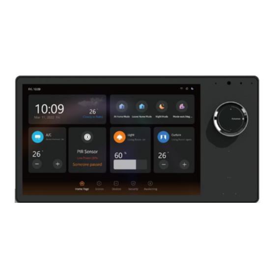
Chapter 1 Product presentation 1.1 Appearance 1.2 Main Features ● With optional Asian | EU | US back base, one design for global users, simple inwall installations. ● 8-inch HD LCD, IPS, multi touch screen, double microphones with noise reduction, built in 2 x 1W speakers, light sensor, temperature and humidity sensor. -
Page 4: Chapter 2 Product Specifications
Chapter 2 Product Specifications... -
Page 5: Chapter 3 Ports And Specifications
Chapter 3 Ports and Specifications 3.1 Interface and ports... - Page 6 Option 1 - US Back Base Option 2 - EU | UK | UAE Back Base Option 3 - Asian Back Base...
-
Page 7: Specifications
3.2 Specifications... -
Page 8: Chapter 4 Installation Instructions
Chapter 4 Installation instructions ● Turn off the main power in the electricity box and confirm the live wire is not alive with a test pencil. ● Check the wires and make sure the wires are in good contact with the terminals and no exposed copper wires. ●... -
Page 9: Installation Drawings
4.1 Installation drawings (Taken EU wall boxes installation as an example.) -
Page 10: Wires Connection Drawing
Note: Make sure the circuit power were cut off before wire connections! Circuit breaker used as disconnected device shall be incorporated in the electrical installation of the building. Depth of the wall box should be more than 50mm. 4.2 Wires connection drawing... -
Page 11: Chapter 5 Operation Guideline
This product can not be used in moisture circumstances such as bathroom. 5.2 Operation guideline *This operation guideline is based on Unihoms ZigBee, Unihoms App,Unihoms cloud platform and Smatek T8E firmware. If any other platforms or firmware, please follow their operation guidelines. - Page 12 when you start it in the first time. You can also get into the network settings from the select menu by swiping down from the top of the LCD screen. (2)There is a wireless wifi connection in the network settings.
- Page 13 You can select it. There will be a QR code showing on the screen after the network connection is done. (3) Start the Unihoms App in your smart phone, select the “ ” at top right corner in the App home page, and then select the...
- Page 14 (4) Scan the QR code on the screen of the product to add it into the Unihoms App. You will find a panel icon in your App. (5) Enter the panel interface in the Unihoms App, you will see gate way and switch icons like and .Click the switch icon to control 2 local switches (load of each switch for lamps should be no more than 200W.).
- Page 15 5s, then the LED indication light flickering which means it is in the set-up mode.) You will see the following pictures in the Unihoms App when you are adding sub devices to the gateway. Make sure the sub devices are in the set-up mode and the LED indication light is flickering.
- Page 16 (7) Click the Done button on the App after you add the sub device successfully. For example (3 Gang Switch) as the following. (8) You could change the name of the sub devices after they are added to the gateway successfully.
- Page 17 Swipe down - sync to have devices and scenes sync to panel. (9) You could change the device type by getting into the device interface in the App. It means the switch is off when it is in grey, and the switch is on when it is in green. You could also set up timers(Schedule) for the switches to realize the automation control.
- Page 18 (10) Tocreatescenes,enterUnihomssmartApp-Scene- Tap-to- Run (not Automation) - create scenes - Launch Tap-to-Run-Then -Runthedeviceandconfiguredifferent devices work at the same time as a scene. And you can rename your scenes. Swipe down and click sync to have your devices and scenes sync to panel, now one tap on panel, whole home automation.
- Page 19 Swipe down - Key Settings to define the right 2 touch scene switches + knob controller by your specific devices or scenes on your App. If there is any questions when you add some other sub devices, please contact us for support.
Need help?
Do you have a question about the T8E and is the answer not in the manual?
Questions and answers