
Summary of Contents for Lubecore 210
- Page 1 General Manual Lubecore_GM_001 Parallel Automated Lubrication System 210 Pneumatic Pump...
-
Page 2: Document Information
Publication date: September 2019 Revisions: TRADEMARKS Lubecore is a trademarked name. Whether Lubecore appears in this document as Lubecore™, Lubecore, Lubecore International or lubecore, all instance of the name are considered trademarked and cannot be used without the express permission of Lubecore International. -
Page 3: Table Of Contents
Lubecore cannot accept liability for any damage arising from the use of this publication. Please contact Lubecore in case of any questions related to the revision of, required service, repairs and or maintenance as described in this publication Table of Contents Parallel Automated Lubrication System .................. - Page 4 3537 General Operation: Automated Lubrication System (ALS) – Pump Mounted Timer ....3638 MKII Progressive Pump Mounted Timer ................3840 General Operation of the Lubecore™ Trailer Timer ............3840 Pump Mounted Timer Connections ..................3941 Electrical wiring connections ..................
-
Page 5: Preface To The Manual
All rights reserved: This document is the property of Lubecore International, Inc. No part of this document may be reproduced or altered, copied and/or published by means of printing, photocopying, microfilm, scanning or any other form of electronic means without prior written permission from Lubecore International, Inc. -
Page 6: Safety Precautions
Safety Precautions 1) Comply with all safety regulations applicable within the locality where all work is performed. 2) Always take the necessary precautions to prevent potentially dangerous situations from occurring during installation, inspection and maintenance. Always apply or use adequate safety measures to prevent personal injury and material damage, before starting work on any piece of the equipment. -
Page 7: Introduction
This ensures an extended operational life and trouble-free operation, even under extreme operating conditions. High Lubecore installation standards along with the use of the correct type of grease and periodic inspections ensures years of trouble-free system operation. Periodic inspections, which... - Page 8 take little time and effort, can be performed during the regular daily circle check by the operator as well as monthly by the maintenance staff.
-
Page 9: The Concept Of Automated Lubrication
The Concept of Automated Lubrication Greases are used where a mechanism can only be lubricated infrequently and where a lubricating oil would not stay in position. They also act as valuable sealants to prevent ingress of water and dust. Equipment requires lubrication for the following reasons: 1) Keep moving components separated. - Page 10 Benefits Automated lubrication Systems by Lubecore™ are designed to ensure the proper quantity of lubricant is applied during equipment operation ensuring: The better distribution of lubricant to moving parts, increases the longevity and reliability of the equipment being lubricated. Automated lubrication systems (ALS) provides higher frequency of lubricant application with nominal quantities of lubricant to sustain the lubrication film while the equipment is in operation.
-
Page 11: General Operation - Automated Lubrication System (Als) - Truck
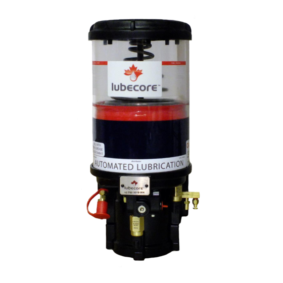
This section describes the general operation of a standard pneumatic lubrication pump with standard components. For details regarding the operation of our other pumps and components, please refer to the appropriate Lubecore manual or contact Lubecore directly. A Lubecore parallel automated lubrication system consists of the following main components. - Page 12 Please refer to the Pump Operation section for more information. Figure 2 – Standard Lubecore Automated Lubrication System Layout on a Truck With the air pressure removed, lubricant pressure in the primary tubing returns to zero and excess lubricant is recycled back into the pump.
-
Page 13: Pneumatic Pump
Lubecore highly recommends using a low-level switch / sensor. The low-level switch / sensor ⑬ helps prevent air from entering the automated lubrication system when the reservoir is not replenished in time. Any lubrication system, independent of brand or operating principle, may be negatively and severely affected by ingress of air into the distribution side of the system. -
Page 14: Pump Operation
Pump Operation Air pressure enters the pump via opening (A), as shown in the illustration on the right, in the bottom of the pneumatic pump. Air pressure requirement; for the pump to generate a sufficient amount of pressure, is a minimum of 6 bar (100 psi). -
Page 15: Reservoir Follower Plate And Guide Rod
The pump is now ready to begin its next a lubrication cycle cycle. Reservoir Follower Plate and Guide Rod The Lubecore ALS pneumatic pump is equipped with a wiper seal and stainless steel follower plate that are being guided and secured by a Dichromate center reservoir guide rod. - Page 16 The primary function of the follower plate is to prevent the funneling effect that may occur during the replenishment of the grease piston in the bottom of the pump. The follower plate is being held in place over a retention spring, by the guide rod. The guide rod guides the follower plate up and down during use and provides an escape for lubricant and air during the filling process.
-
Page 17: Pump Mounting Gasket
(10.063) The Lubecore™ pneumatic pump is equipped with nylon bushings, washers and a foam insert to prevent damage caused by the buildup of moisture, and to isolate the pump from the mounting surface. The isolation of the pump from the mounting surface eliminates metal-to-... -
Page 18: Timer Operation
“working phase”. If the system has been equipped with a Lubecore Smart Switch, the light will be illuminated during working phase until the pressure switch is closed. Depending on the size of the lubrication system, this may take a few seconds. -
Page 19: Performing A Test Cycle
Performing a Test Cycle A single manual “test cycle” can be performed on the timer without connecting to a computer. There are two ways to initiate a test cycle. 1) The truck timer has been equipped with a red test cycle switch in the timer cover. 2) A Smart Switch can be installed in the dashboard. -
Page 20: Smart Switch Option
Smart Switch Option To engage a test cycle with the external switch: 1) Set ignition to auxiliary position and ensure that there is a minimum of 100 Psi of pressure in the onboard air tank. 2) Press the Smart Switch and hold for 3 seconds. While depressed, the light will momentarily illuminate, until the pressure switch closes, this communicates to the operator that a test cycle has been initiated. -
Page 21: Communication Light And Audible Signals
Refer to the installed features to check if a low-level switch or pressure switch are present in the system. The Smart Switch, when installed, is normally located on the dashboard. A label surrounding the switch indicates the relationship to the Lubecore™ automated lubrication system. Light illuminates for 3 seconds when ignition is turned –SYSTEM OK. -
Page 22: Timer Service Report
Note: In case of low lubricant level, filling the reservoir will automatically resolve the error and normal operation continues. However, after filling the reservoir the LED will switch off only after completing a normal automated lubrication cycle. (A test cycle will not reset the LED or alarm.) Timer Service Report The timer is equipped with a real-time clock (RTC), which enables more accurate record... -
Page 23: Programming The Mkii Truck Timer
Programming the MkII Truck Timer The timer can be programmed using a CLS Dongle Timer Interface Unit and a computer running Microsoft™ Windows™ with USB capability. For a more in-depth explanation on how to use the Dongle, please see the Timer Programming manual. Using the CLS Dongle Timer Interface Unit, the timer can both be programmed and reviewed for lubrication system performance. - Page 24 Quick Install Guide for Lubecore Timer Interface Dongle (for Windows™ Operating Systems only): Load the CD into the CD drive In My Computer, double-click the CD drive location to open the CD file. In the CD folder, select the folder that matches the version of Windows installed on your computer.
-
Page 26: Electrical Connections Before September 2019
To ensure proper timer operation without a low-level switch, a jumper wire must be installed between pin #7 and pin #3 at the timer plug end. Figure 2022 Common Electrical Schematic for a Lubecore Truck Timer September 2019 and earlier. -
Page 27: Truck Timer Terminal & Wiring Identification Before September 2019
Truck Timer Terminal & Wiring Identification Before September 2019 Table 1 – Terminal and Wire Identification Table September 2019 and Earlier Mark II Timer Plug (Used from 2010 to September 2019... -
Page 28: Electrical Connections After September 2019
To ensure proper timer operation without a low-level switch, a jumper wire must be installed between pin #7 and pin #3 at the timer plug end. Figure 21 Common Electrical Timer for a Lubecore Truck Timer September 2019 and onward... -
Page 29: Truck Timer Terminal & Wiring Identification After September 2019
Truck Timer Terminal & Wiring Identification After September 2019 Table 2 Terminal and Wire Identification Table September 2019 and Later Mark II Timer Plug (Used from September 2019 - Present Pressure Switch Solenoid/Motor + Solenoid/Motor - Table 3 – Timer Technical Specifications Timer Specification Based on Model (12.016 &... -
Page 30: Basic Timer Operation
Basic Timer Operation General Operation of the Lubecore™ Basic Timer Lubecore™ recognized that in today’s market price is a major concern. In the world of automated lubrication systems, this means that some customers may choose to forego enhanced features such as low level and pressure alarms to reduce the cost of their systems. - Page 31 Performing a test cycle The basic timer has a red test cycle switch in the timer cover, similar as to the MKII truck timer. This red button can be used to initiate a single lubrication cycle. An accelerated test cycle is not available. Red Test Button To prevent accidental operation of the ALS, the red button has been set flush with the cover.
- Page 32 Electrical Connections Basic Timer A standard electrical schematic is shown below. For schematics related to the exchange of timers in other systems, please visit www.lubecore.com or contact Lubecore directly. – 12.015 Timer Schematic Figure 2628 Table 5 – Timer electrical connections...
- Page 33 Air solenoid Schematic Pressure Switch A standard Lubecore automated lubrication system is equipped with a pressure switch. Once the lubrication system has reached nominal operating pressure, the pressure switch provides feedback to the timer. The pressure switch is, for a pneumatically operated pump usually located in the front- center of the pump.
- Page 34 Low Level Switch & Sensor The Lubecore ALS pneumatic pump can be equipped with a low-level switch/sensor. The low-level switch/sensor can be found on the right side of the pneumatic pump, just below the reservoir. Once the follower plate reaches the minimum reservoir grease level, the low-level switch/sensor opens.
- Page 35 Trouble Shooting - Truck Timer 12.016 & 12.036 For certain sections in this trouble shooting overview for the truck timer, the following tools might be required: Multi meter / Test-light, pressure gauge, 10cm / 5-inch-long loop wire or metal paperclip. Table 6 -Truck Timer Trouble Shooting Guide Problem Diagnosis / Check Item...
- Page 36 For details regarding the operation of our other pumps and components, please refer to the appropriate Lubecore manual or contact Lubecore directly. A Lubecore automated lubrication system consists of the following main components.
- Page 37 With the air pressure removed, lubricant pressure in the primary tubing returns below 30bar and excess lubricant is recycled back into the pump. Once grease pressure has dropped below 30bar, the re-loading process within the injectors begins. Figure 31 – Standard Lubecore Automated Lubrication System Layout for a Trailer with Pump Mounted Timer...
- Page 38 MKII Progressive Pump Mounted Timer General Operation of the Lubecore™ Trailer Timer Following is a functional description of the Lubecore™ pump mounted timer which was designed to replace trailer timer applications but may be used on any system. This information pertains to model 12.079.
- Page 39 Braking System (ABS), to the nose or junction box of a solenoid and low level trailer or to a rechargeable power supply. Depending on connections a variety of harnesses and wiring are available, please contact Lubecore for further details. 3 wire harness connection to power harness Figure...
- Page 40 Performing a test cycle - electrically operated A single “test cycle” can also be performed with the timer connected to power. The timer can be tested by means of a magnet. See detailed operational functions and programming on pages 31-34 Figure 3539 Test Magnet Location on...
- Page 41 Electrical Connections A schematic of the 10-30 VDC trailer timer is shown below. The timer itself is permanently sealed (potted) with the trailer timer enclosure. Power and ground are connected via Deutsch DT sealed connectors. A second connection is available for an optional low-level sensor. The 3 wires provide a sensor with power, ground, and a return signal contact for the timer.
- Page 42 Timer Setting and Display Operation The trailer timer is equipped with a 7-segment digital display. This display indicates power, operation and errors. It is also used to facilitate timer setting. Following is an overview of possible display codes: - No segments lit. Power is “Off”. - Solitary LED (Bottom right corner of the Segmented display) momentarily stays on (5 Seconds) performing a self-check.
- Page 43 For correct operation of the pump (T1) the “Pause”, and (T2) “Work” times must be set using the magnet. Follow enclosed instructions to program the timer. With power on (ignition) hold the magnet against the Lubecore logo on the timer enclosure near the segment display. After 3 seconds and with about 3 second steps thereafter, the segment display will change as follows: 1) To start a single test cycle, place the magnet on the Lubecore logo.
- Page 44 4) To change the pump interval / pause time (T1), place the magnet on the Lubecore logo until 4 bars light up. When the display shows 4 bars, remove the magnet to go into time selection mode. A one second touch or...
- Page 45 Our team of engineers is continually working to improve the system to ensure that the Lubecore ALS remains the best system available. To extend the life of your Lubecore ALS and to prevent any potential service issues, please review the following:...
- Page 46 Injectors The Lubecore™ Injector is the core component and forms the basis of the principle on which the operation of the automated lubrication system is based. Lubecore automated lubrication system injectors operate parallel to each other; all injectors dispense lubricant simultaneously.
- Page 47 Table 7 – Available Injector Sizes Description Part Number Output Size (cc/Stroke) Injector #0 11.800 0.025 Injector #1 11801 0.050 Injector #2 11.802 0.100 Injector #3 11.803 0.150 Injector #4 11.804 0.200 Injector #5 11.805 0.250 Injector #6 11.806 0.300 Injector #7 11.807 0.350...
- Page 48 If pressure is not reached review error recovery section of this manual or contact Lubecore for assistance. Note: Principles for purging air from an automated lubrication system are the same whether the ALS is pneumatic, electric, hydraulic or hybrid.
- Page 49 Filling the Reservoir When either the timer indicates that the level switch has been triggered or during a system inspection it’s visible that the follower plate has reached minimum level, the pumps reservoir needs to be refilled with an appropriate NLGI / EP lubricant. For refilling the reservoir, please follow the steps as described below to ensure that no contaminants and/or air enter the lubrication system.
- Page 50 During filling of the reservoir or immediately after the maximum level has been reached, some lubricant may be expelled at the overflow opening. The overflow is located on the left side of the pump where the pump base meets the reservoir. Air possibly trapped under the follower plate and excess lubricant shall come out at this opening.
- Page 51 Technical Specifications Table 8 – Pneumatic Pump Technical Specs Part Number 50.050 50.060 Reservoir Capacity 4kg / 8.8lbs 6kg / 13.2lbs Main Piston Air Grease Pressure Ratio 10:1 Maximum Grease Pressure 1600psi / 110bar Pump Grease Output 40cc / stroke Operated Temperature Range -25°C to 80°C (-13°F to 160°F) Lubricant Grade...
- Page 52 Figure 50 – General Dimensions of a 4kg Pump...
- Page 53 Lubrication Point Maps, Samples & General Parts...
- Page 55 Figure 51 – Possible Number of Grease Points on a Tandem Axle Tractor...
- Page 57 Figure 52 – Possible Lubrication Points and Identification of a Tandem Axle Trailer with Lift Steer Axle.
- Page 58 Parallel - Single Line common parts list Category Part# Part Description Injectors 11.800 Injector #0 11.801 Injector #1 11.802 Injector #2 11.803 Injector #3 11.804 Injector #4 11.805 Injector #5 11.806 Injector #6 11.807 Injector #7 11.808 Injector #8 11.885 Injector #8.5 11.809 Injector #9...
- Page 59 Category Part# Part Description Lubrication Point Compression Fittings Continued 20.024 5mm x 1/8 (M) BSPT Compression 90° Elbow - Brass 20.025 5mm x 5mm Compression Union - Brass 20.056 5mm x M6 x 1 (M) Compression Conical - Brass Lubrication Point Secondary Tubing 30.003 5mm Single Secondary Lining - Black 30.004...
- Page 60 Head-office: Lubecore International, Inc. 7065 Twiss road Campbellville, Ontario Canada L0P-1B0 Phone: 1-905-864-3110 E-mail: Info@Lubecore.com Web site: http://www.lubecore.com NEXT GENERATION AUTOMATIC LUBRICATION...
Need help?
Do you have a question about the 210 and is the answer not in the manual?
Questions and answers