Table of Contents
Advertisement
Quick Links
fruku.club
CC-BY-SA 4.0
/// Evi Build Guide
Thank you for choosing one of my products! Please follow this build guide
thoroughly, even if you are an experienced DIYer. The order in which
components are placed on the PCB is meant to make the assembly process as
easy as possible.
Disclaimer:
Everything you do while assembling the kit/PCB is at your own risk. Fruku is not
responsible for anything that might happen during assembly of the kit/PCB.
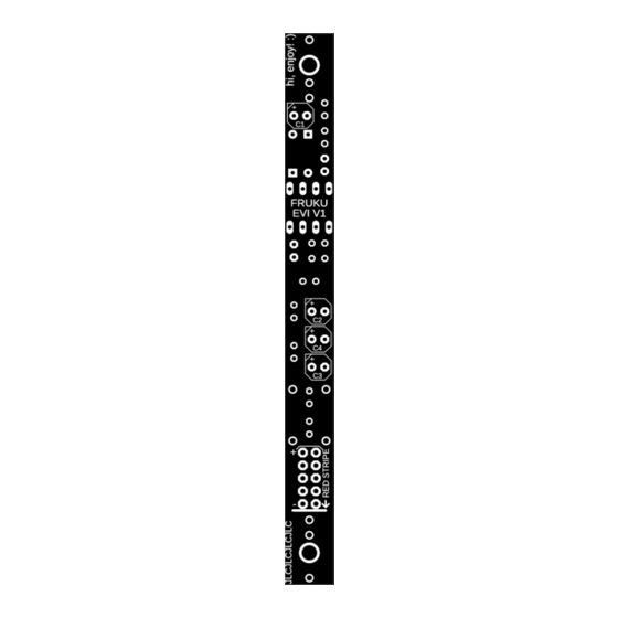
PCB for reference:
Advertisement
Table of Contents

Summary of Contents for Fruku Evi
- Page 1 PCB is meant to make the assembly process as easy as possible. Disclaimer: Everything you do while assembling the kit/PCB is at your own risk. Fruku is not responsible for anything that might happen during assembly of the kit/PCB. PCB for reference:...
- Page 2 /// Resistors Start with soldering the resistors, these need to be placed “standing up”. Make sure the “bend” is as low as possible (see picture). The values of the resistors are written on the tape. If you are unsure, use a Multimeter to check the value. Check the BOM file, there you will find which resistor values correspond to the part numbers written on the PCB.
- Page 3 /// Capacitors Now solder the capacitors, look at the BOM for the values and placements. Please take notice of the positive and negative side with the electrolytic capacitors. The electrolytic capacitors need to be placed on the bottom side of the PCB.
- Page 4 /// Jack sockets & LED Insert the jack sockets and the LED (beware of the orientation of the LED) on the top side of the PCB. DON'T solder yet! Now place the front panel over the jack sockets and use the two nuts from the jack sockets to hold the front panel in place.
- Page 5 Turn on the power. Check if nothing blows! If all is well, proceed: Patch :) /// Troubleshooting If the module does not work, check the orientation of the IC, electrolytic capacitors and diodes. Check your soldering. It should be perfect, like in this picture: fruku.club info@fruku.club...
Need help?
Do you have a question about the Evi and is the answer not in the manual?
Questions and answers