Table of Contents
Advertisement
Quick Links
General Installation Guide for PTO's
1 - ATTENTION: SAFETY INFORMATION
- The PTOs should be mounted by quali ed personnel.
- Use suitable tools and measurement instruments.
- Use personal protection and precautions set out by current regulation on safety in the workplace.
- Ensure the system or the PTO cannot involuntarily be started up.
- Do not assemble the PTO or parts of the PTO or conduct maintenance work when the engine is on.
- Ensure all the components have been assembled properly and the level of oil in the gear box has been topped up before starting up the
vehicle: Incorrect assembly of the PTO may cause the PTO and/or the gearbox to break and damage other parts of the vehicle.
- The splined shaft (male or female) protruding from the PTO rotates with no protection when the pump has not been assembled.
Avoid any contact between the shaft and any object and, more importantly, protect the working area to prevent contact with body parts or
clothing.
- Install the pump or the cardan shaft only when the engine is o and the PTO has been disconnected.
- The gearbox or the PTO may attain high very temperatures after prolonged use of the vehicle or the PTO. It is therefore necessary to take
all the necessary precaution measure to prevent burns. Wait for the mechanical parts to cool down to temperatures appropriate for skin contact
- Some PTOs are considerably heavy and to assemble and disassemble them it is necessary to use adequate lifting or resting sys
prevent crushing hazards, it may be necessary for two people to carry out the operation.
- Any waste oil that has not been used should be processed according to the directives included in the current regulation on the disposal of special waste.
2 - INDICATIVE ASSEMBLY POSITIONS OF THE PTOS
ASSEMBLY OF THE UPPER PART
ASSEMBLY OF THE LOWER PART
ASSEMBLY OF THE LEFT SIDE
ASSEMBLY OF THE REAR
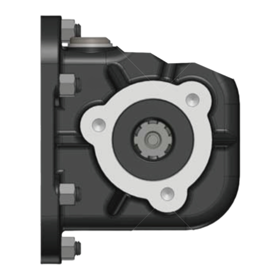
MOST COMMON PTO SHAFT
OUTLET VERSION
SETTING THE INDUSTRY STANDARD
ASSEMBLY OF THE RIGHT SIDE
OUTLET REAR SHAFT
OUTLET FRONT SHAFT
Male shaft 8x32x36 (ISO14) Rear outlet
This version always requires
the ange (114...)
Edbro plc
Nelson Street, Bolton BL3 2JJ, UK
Tel: +44 (0) 120 4528888 Fax: +44 (0) 120 4531957
Spares fax: +44 (0) 120 4393561
Web: www.edbro.com
RULES APPLYING TO THE DIRECTION
OF ROTATION OF THE PTO
VERSION 13
Male shaft 6x21x25 (ISO14)
Rear outlet
VERSION 15
Technical specifications are subject to change without notice.
PTO 01-01
OUTPUT SHAFT
CLOCKWISE rotation
Application - LEFT pump
CLOCKWISE
ANTICLOCKWISE
ANTICLOCKWISE rotation
Application - RIGHT pump
VERSION 14
Male shaft 6x21x25 (ISO14)
Front outlet
VERSION 17
Female hub 8x32x36 (ISO14)
Rear outlet
Rev1, July 2011
Advertisement
Table of Contents

Summary of Contents for Edbro PTO 01-01
- Page 1 PTO 01-01 General Installation Guide for PTO’s 1 - ATTENTION: SAFETY INFORMATION - The PTOs should be mounted by quali ed personnel. - Use suitable tools and measurement instruments. - Use personal protection and precautions set out by current regulation on safety in the workplace.
- Page 2 PTO 01-01 General Installation Guide for PTO’s 3 - GENERAL INFORMATION TO MOUNT POWER TAKE-OFFS - Carefully follow these general assembly instructions, both as far as the safety precautions and the assembly stages of the PTOs are concerned. - The general indications do not replace speci c instructions contained in the PTOs, in the assembly kit or in the various assembly accessories (adapters, auxiliary shafts, etc).
- Page 3 PTO 01-01 General Installation Guide for PTO’s 5 - INSTALLATION OF REAR MOUNT PTOS It is necessary to check and follow the speci c instructions contained in the adapters and the auxiliary shafts. tions contained in the adapters and the auxiliary shafts. The indications below are meant as a guide.
- Page 4 PTO 01-01 General Installation Guide for PTO’s 7 - CHECKS 7.1 - Checking the coupling Connect and disconnect the PTO a few times (follow the paragraph HOW TO USE THE PTO) to check the coupling system is working properly Any anomalous noise produced during coupling is only due to the fact that the PTO’s gearings are not completely still and therefore to the fact that the vechile’s clutch is not working properly.
Need help?
Do you have a question about the PTO 01-01 and is the answer not in the manual?
Questions and answers