Table of Contents
Advertisement
Quick Links
Advertisement
Table of Contents

Summary of Contents for Böker Druck PV624
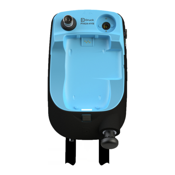
- Page 1 PV624 Hybrid Pressure Station Instruction Manual Druck.com...
-
Page 2: Table Of Contents
Contents Overview Introduction Other Module Options Summary of Functions Quick Reference Data Equipment in the Box Safety 1.6.1 General Warnings 1.6.2 Pressure Warnings 1.6.3 Electrical Warnings 1.6.4 Software Configuration and Security Over-voltage Categories Product Label Instrument Parts Introduction PV624 Parts 2.2.1 Pressure Release Knob and Barometric Port 2.2.2... - Page 3 4.3.5 DPI620G Calibrator: Step Mode (Percent Step) 4.3.6 DPI620G Calibrator: Step Mode (Defined Step) 4.3.7 DPI620G Calibrator: Step Mode (Point Step) 4.3.8 DPI620G Calibrator: Set the PM620/PM620T Module to Zero 4.3.9 DPI620G Calibrator: Set the Pressure Type 4.3.10 DPI620G Calibrator: Resolution Utility (Channel Settings) 4.4.1 DPI620G Calibrator: Set the Pressure Function...
- Page 4 Specification PV624 Model 9.1.1 Pressure Data (PV624) PM620/PM620T Module 9.2.1 Pressure Data (PM620/PM620T modules) Appendix A. COMPLIANCE STATEMENTS FCC (USA) CANADA Copyright 2023 Baker Hughes Company. English–PV624 Instruction Manual | v...
-
Page 5: Overview
Introduction 1. Overview This manual gives operation procedures and safety information for the PV624 pressure station. It is the responsibility of the user to make sure that only approved personnel can operate and do maintenance on the equipment. Note: Before you operate the equipment, read and obey all warnings and cautions given in the Quick Start and Safety Manual for this instrument. -
Page 6: Summary Of Functions
Chapter 1. Overview DPI620G Advanced modular calibrator, DPI620G (user manual - K0541): This is a battery-powered instrument for electrical measure and source operations. It also supplies the power and user interface functions for all the add-on modules. You can use the touch-screen to show up to six different parameters. -
Page 7: Quick Reference Data
Quick Reference Data 1.4 Quick Reference Data PV624: Pneumatic pressure station -0.9 barg to 20 barg (-12.328 to 300 psig) Recommended pressure modules (PM620/PM620T) PV624 0.7 barg to 20 barg (10.15 to 300 psig) full scale CAUTION To prevent damage to the PM620/PM620T module, only use it within the specified pressure limit on the label. -
Page 8: Safety
Chapter 1. Overview 1.6 Safety Before use of the instrument, make sure to read and understand all the related information. This includes: the applicable local safety procedures, this publication, and the instructions for the accessories/options/equipment that are to be used with it. 1.6.1 General Warnings WARNING It is dangerous to ignore the specified limits for the instrument or... -
Page 9: Software Configuration And Security
Over-voltage Categories WARNING External circuits must have applicable insulation to the mains. This instrument uses a Lithium-Polymer (Li-Polymer) battery pack. To prevent an explosion or fire, do not short circuit, do not disassemble, and keep safe from damage. To prevent an explosion or fire, only use the Druck specified battery (IO624- BATTERY) and power supply (IO610E-PSU) rated for this instrument. -
Page 10: Product Label
Chapter 1. Overview 1.8 Product Label 1. Identification code of instrument 2. Max. working pressure of instrument 3. Serial number of the instrument 4. Date of Manufacture: Month, Year 5. Maximum Working Pressure is 1.2 x value of full scale pressure range 6. -
Page 11: Instrument Parts
Introduction 2. Instrument Parts 2.1 Introduction This chapter identifies of the different parts of PV624 instrument. 2.2 PV624 Parts Test port: Pressure connection (G1/8 or 1/8NPT) to attach the device under test; see Section 2.2.2. Pressure and electrical connections for a PM620/PM620T module. -
Page 12: Pressure Release Knob And Barometric Port
Chapter 2. Instrument Parts 2.2.1 Pressure Release Knob and Barometric Port The pressure release knob is on the bottom right of the instrument. To release pressure, slowly turn the valve knob counterclockwise one full rotation. Make sure the system is sealed before pressure generation: fully turn the pressure release knob in the clockwise direction to close. -
Page 13: Bluetooth Button
PV624 Parts 2.2.4 Bluetooth Button The Bluetooth button is next to the Battery Charge Indicator. On a PV624 that has Bluetooth installed, you can disconnect the PV624 and DPI620G from each other and then push the button to select the Bluetooth mode. A wireless communication channel then becomes available. -
Page 14: Status Led
Chapter 2. Instrument Parts 2.2.8 Status LED The status LED shows the different operational modes of the PV624. Refer to image in Section 2.2.9. It has three different indications as described in Table 2-2. Table 2-2: Status Indication LEDs Indication LED Color Remarks Status - Power ON... -
Page 15: Pneumatic Pressure Operation
Introduction 3. Pneumatic Pressure Operation 3.1 Introduction This chapter gives examples of how to connect and use the PV624 pressure station with the DPI620G, to make the necessary pressure or vacuum conditions. Before you start: • Read and understand the “Safety” section. •... -
Page 16: Use Of Blanking Plug
Chapter 3. Pneumatic Pressure Operation 3.3.1 Use of Blanking Plug A blanking plug seals the test port and stops access of foreign matter into the port. It is good practice to attach the blanking plug when the test port is not in use. To remove the blanking plug, hold the adapter firmly in one hand and turn the locking collar in a clockwise direction. -
Page 17: Remove Device Under Test
Attach/Remove the Device Under Test 3.3.4 Remove Device Under Test To remove a device, release the pressure first (Section 3.2): To remove the device under test, hold it firmly while you turn the locking collar fully clockwise. Attach the Blanking Plug to seal and protect the socket if the instrument is not required for immediate use. -
Page 18: Assembly Instructions
Chapter 3. Pneumatic Pressure Operation 3.4 Assembly Instructions Step Procedure Energize (power on) both devices: Push the power button on the DPI620G until the device energizes. Do this again on the PV624. Lower the DPI620G calibrator into the molded compartment. Push on the bottom end of the calibrator until it latches in position. -
Page 19: Pressure Or Vacuum Operation
Pressure or Vacuum Operation 3.5 Pressure or Vacuum Operation After an applicable device correctly attaches to the test port (Section 3.3) and the DPI620G to the PV624 pressure station, use this procedure to set the necessary pressure or vacuum. Step Procedure Seal the system: turn the pressure release knob clockwise (1 turn). -
Page 20: Pressure Calibrator Operation (Dpi620G)
Chapter 4. Pressure Calibrator Operation (DPI620G) 4. Pressure Calibrator Operation (DPI620G) 4.1 Introduction This section gives examples of how to use the pressure station to do pressure calibrations with the DPI620G calibrator and the applicable pressure module (PM620/PM620T). Before you start: •... -
Page 21: Pm620/Pm620T Module Parts
Basic Channel Settings 4.2.2 PM620/PM620T Module Parts Pressure module (PM620/PM620T) with a pressure connection, reference port (a) and a label. The label includes: Pressure range. Example: 20 bar g (g: gauge; a: absolute); serial number (S/N); manufacturer: name, address, website CAUTION To prevent damage to the PM620/PM620T module, only use it within the specified pressure limit on the label. -
Page 22: Dpi620G Calibrator: Process
Chapter 4. Pressure Calibrator Operation (DPI620G) 4.3.3 DPI620G Calibrator: Process Process options relate to the measured values for individual channel functions. Options that are available depend on the function and include: Option Description Tare Use this option to set a temporary value for zero. This makes an adjustment to all subsequent readings on the display. -
Page 23: Dpi620G Calibrator: Step Mode (Nudge)
Basic Channel Settings 4.3.4 DPI620G Calibrator: Step Mode (Nudge) This is the default Step Mode option. This lets the source value be done in increments by a set step value. This example shows the sequence to set the Nudge step mode: Select Nudge and Pressure channel Channel Settings... -
Page 24: Dpi620G Calibrator: Step Mode (Percent Step)
Chapter 4. Pressure Calibrator Operation (DPI620G) 4.3.5 DPI620G Calibrator: Step Mode (Percent Step) This mode lets the source value increase in increments, in steps that relate to a set percentage of the span of values. The LOW, HIGH and STEP SIZE value can be set. This example shows the sequence to set the PERCENT STEP mode: To access the SETTINGS menu refer to Section 4.3.1 on page 17. -
Page 25: Dpi620G Calibrator: Step Mode (Defined Step)
Basic Channel Settings 4.3.6 DPI620G Calibrator: Step Mode (Defined Step) This mode lets the source value increase in set increments (steps) within the span limits. The LOW, HIGH and STEP SIZE value can be set. This example shows the sequence to set the Defined step mode: To access the SETTINGS menu refer to Section 4.3.1 on page 17. -
Page 26: Dpi620G Calibrator: Step Mode (Point Step)
Chapter 4. Pressure Calibrator Operation (DPI620G) 4.3.7 DPI620G Calibrator: Step Mode (Point Step) This mode makes the source value increase and decrease in a set number of points. When Direction is set to Up the number of points will increase from LOW to HIGH. When Direction is set to Down, the number of points will be from the HIGH to LOW value. -
Page 27: Dpi620G Calibrator: Set The Pm620/Pm620T Module To Zero
Basic Channel Settings 4.3.8 DPI620G Calibrator: Set the PM620/PM620T Module to Zero Use this option to write a new zero pressure value to the PM620/PM620T module in use. This option only affects gauge type modules. It is recommended that all gauge sensors are zeroed at the start of each day before use. This example shows the sequence to set the Point step mode: To access the SETTINGS menu refer to Section 4.3.1. -
Page 28: Dpi620G Calibrator: Set The Pressure Type
Chapter 4. Pressure Calibrator Operation (DPI620G) 4.3.9 DPI620G Calibrator: Set the Pressure Type There are two types of pressure sensor: Gauge and Absolute. Both sensors can be set up to use a Pseudo mode. The Pseudo mode combines the original sensor type and barometric reading from the PV624, to show the Pseudo pressure reading (Pseudo-abs/Pseudo-gauge). -
Page 29: Utility (Channel Settings)
Utility (Channel Settings) 4.4 Utility (Channel Settings) The Tasks menu gives access to these utilities shown below: 4.4.1 DPI620G Calibrator: Set the Pressure Function This example shows the sequence to set the pressure function. It is a similar procedure for other functions;... -
Page 30: Dpi620G Calibrator: Set The Pressure Units
Chapter 4. Pressure Calibrator Operation (DPI620G) 4.4.2 DPI620G Calibrator: Set the Pressure Units This example shows the sequence to set the pressure units. Select the Pressure Tap the Task icon Select CUSTOM TASK channel Select UNITS Select the Pressure unit 4.4.3 DPI620G Calibrator: Set Up a Leak Test It is recommended a Leak Test be done before the completion a PV624 calibration or operation. - Page 31 Utility (Channel Settings) Set the Leak Test options When you have set the Utility to Leak Test, you can use these options from the Channel Settings (See “Basic Channel Settings” on page 17.): WAIT TIME Before you start a Leak test, you must let the pressurized system become stable before the test starts.
-
Page 32: Dpi620G Calibrator: Set Max/Min/Mean Test
Chapter 4. Pressure Calibrator Operation (DPI620G) 4.4.4 DPI620G Calibrator: Set Max/Min/Mean Test When you select this utility, the real-time minimum, maximum, and average values of the measured signal is shown in addition to the live measured reading. For more information refer to the user manual - K0541. -
Page 33: Example Procedure: Relief Valve Test
Utility (Channel Settings) 4.4.5 Example Procedure: Relief Valve Test Pressure relief valves are safety devices that open automatically at a specified pressure to prevent over-pressure conditions in connected equipment. The Relief Valve Test measures the actuation pressure of pressure relief valves. The user selects either rising or falling mode operation to test positive or negative pressure relief devices. -
Page 34: Dpi620G Calibrator: Set Up A Switch Test
Chapter 4. Pressure Calibrator Operation (DPI620G) 4.4.6 DPI620G Calibrator: Set Up a Switch Test Pressure switches open or close an electrical circuit when the applied pressure exceeds a specified threshold. Hysteresis is the difference between the applied pressures that start and reset the pressure switch, as illustrated in Figure 4-3. - Page 35 Utility (Channel Settings) Figure 4-2: Switch test accuracy setting Refer to Figure 4-3 for the screens to which these instructions relate: Select CALIBRATOR on the dashboard. Select the P1 channel on the TASK SETTINGS screen. Select UTILITY on the CHANNEL SETTINGS screen. Select SWITCH TEST.
- Page 36 Chapter 4. Pressure Calibrator Operation (DPI620G) Figure 4-3: Switch test example (Continued) Tap the RAMP DOWN icon to decrease pressure in the PV624. Refer to Figure 4-2 on page 31 for the set accuracy (measured in bar.) The display shows: •...
-
Page 37: Settings Menu
Settings Menu 4.5 Settings Menu Use the Settings menu to access the STATUS, CONNECTIONS and ADVANCED sub menu. 4.5.1 Overview of Settings Menu The STATUS menu has the option to view the BASE and BAROMETER status and data. The CONNECTIONS menu has the option to view the Bluetooth connection data. The ADVANCED menu has the option to do the barometer calibration of PV624 and to adjust the barometer calibration dates. -
Page 38: Dpi620G Calibrator: View The Base Status And Barometer Status
Chapter 4. Pressure Calibrator Operation (DPI620G) 4.5.3 DPI620G Calibrator: View the Base Status and Barometer Status This example shows the sequence to see the BASE and BAROMETER STATUS. To access the STATUS menu refer to Section 4.5.1 on page 33. Scroll down list and tap Tap Base status Tap Status icon... -
Page 39: Dpi620G Calibrator: Connect Pv624 Via Bluetooth
Settings Menu 4.5.4 DPI620G Calibrator: Connect PV624 via Bluetooth This example shows the sequence to use Bluetooth to connect the DPI620G to the PV624. The Bluetooth option in PV624 lets signals move between the device and the DPI620G, with no physical connection. -
Page 40: Dpi620G Calibrator: Adjust The Barometer Calibration Date And Interval
Chapter 4. Pressure Calibrator Operation (DPI620G) 4.5.5 DPI620G Calibrator: Adjust the Barometer Calibration Date and Interval This example shows the sequence to set the barometer calibration date and interval. To access the ADVANCED menu refer to Section 4.5.1 on page 33. Enter PIN 4321 Tap Perform pressure cal Tap Advanced menu... -
Page 41: Example Procedure: Barometer Calibration
Settings Menu To change the BARO CAL INTERVAL. Tap BARO CAL INTERVAL to set the number of days. Set the necessary number of days. Tap the to set the changes. 4.5.6 Example Procedure: Barometer Calibration This example shows the procedure to calibrate the internal barometer. Figure 4-4: Barometer calibration setup To calibrate the internal barometer sensor of the PV624, make sure the correct pressure connection (refer to “Pressure Release Knob and Barometric Port”... - Page 42 Chapter 4. Pressure Calibrator Operation (DPI620G) CALIBRATION - Barometer screen has two sections. The top section shows the read value from the internal PV624 barometer. The below calibration point section gives the following information: • Function minimum range (or negative full-scale) value. •...
- Page 43 Settings Menu The CAL VALUE screen shows the stable measured value. You can use the value read on the external pressure source to change this value: tap the icon to continue with this measured value. The screen shows the message “Touch to apply entered calibration point value”.
-
Page 44: Help Menu
Chapter 5. Help Menu 5. Help Menu 5.1 Overview The Help menu provides related information on how to use the instrument. Tap the icon on the dashboard to access the help menu. All the information necessary to operate the PV624 and DPI620G is in this menu and gives the following options. -
Page 45: Maintenance Procedures
Introduction 6. Maintenance Procedures 6.1 Introduction This chapter gives procedures for the maintenance of the instrument and to keep it in a good condition. Send the instrument to the manufacturer or an approved service agent for all repairs. Table 6-1 summarizes manufacturer recommended maintenance tasks for the PV624. Table 6-1: Maintenance tasks Task Period... -
Page 46: Leak Test
Chapter 6. Maintenance Procedures 6.5 Leak Test Table 9-2 gives the maximum leak rates for each type of PV624 pressure station. 6.5.1 Preparation To do a leak test, use these items: • a DPI620G calibrator • the applicable PM620/PM620T module for the pressure station: •... -
Page 47: Replacement Of Battery
Replacement of Battery 6.6 Replacement of Battery To remove and replace the battery: Use a screwdriver to loosen the two screws until you release the battery cover. Pull on the two screws to remove the cover, then pull the battery out. When you insert the battery make sure its electrical connections point inwards. -
Page 48: Test Procedures
Chapter 7. Test Procedures 7. Test Procedures 7.1 Overview This chapter gives examples of how to complete a documented calibration of Device Under Test (DUT) equipment or of assets using specified test procedures. When you use test procedures to calibrate DUTs, the test details and results of the calibration are saved in DPI620G memory. -
Page 49: Error Messages
PV624 Error Codes 8. Error Messages An error message is information displayed to the user when an unexpected condition occurs. Error message indicates that an action cannot be completed because of a system error. Error messages are used when user intervention is necessary, to show that a necessary operation did not operate correctly. - Page 50 Chapter 8. Error Messages Table 8-1: General error codes Code Type Message Corrective/Recommended Action Not Recoverable. Please contact Optical Board Not Base error – optical sensor failed service center. Found Check Battery is connected Base Error - Battery Battery Communication correctly.
- Page 51 PV624 Model 9. Specification 9.1 PV624 Model Refer to the below table 9-1 for a general specification of the PV624 pressure station. Table 9-1: General specification Operating temperature 0 to 50°C (32 to 122°F) Storage temperature -20 to 70°C (-4 to 158°F) Ingress protection IP54 Humidity...
- Page 52 Chapter 9. Specification 9.1.1 Pressure Data (PV624) Table 9-2: Pressure specification PV624 Hybrid pressure generation range -0.9 barg to 20 barg 0.7 barg(10 psig), 1 barg(15psig), 2 Hybrid pressure generation compatible barg/abs(30 psig/abs), 3.5 barg/abs(50 PM620 (FS) pressure ranges psig/abs), 7 barg/abs(100 psig/abs), 10 barg/abs(150 psi), 20 barg/abs(300 psig/abs).
- Page 53 PM620/PM620T Module 9.2 PM620/PM620T Module Refer to the table 9-3 for general specification of the PM620/PM620T module. Table 9-3: General specification -10 to 50°C (14 to 122°F) Operating temperature Calibrated range: 0 to 50°C (32 to 122°F) Storage temperature -20 to 70°C (-4 to 158°F) Ingress Protection IP54 Humidity...
- Page 54 Appendix A. COMPLIANCE STATEMENTS Appendix A. COMPLIANCE STATEMENTS A.1 FCC (USA) Federal Communication Commission Interference Statement This equipment has been tested and found to comply with the limits for a Class B digital device, pursuant to Part 15 of the FCC Rules. These limits are designed to provide reasonable protection against harmful interference in a residential installation.
- Page 55 CANADA A.2 CANADA ISED Canada Statement This device complies with Industry Canada's license-exempt RSSs. Operation is subject to the following two conditions: This device may not cause interference; and This device must accept any interference, including interference that may cause undesired operation of the device.
- Page 56 Office Locations Services and Support Locations Copyright 2023 Baker Hughes Company. This material contains one or more registered trademarks of Baker Hughes Company and its subsidiaries in one or more countries. All third- party product and company names are trademarks of their respective holders. bakerhughes.com 174M7583 PV624 Revision - | English...
Need help?
Do you have a question about the Druck PV624 and is the answer not in the manual?
Questions and answers