
Related Manuals for INVT EVC16 Series


Summary of Contents for INVT EVC16 Series
- Page 1 EVC16 Series of electric vehicle AC power supply charger Installation and Operation Manual EVC16-AW7KGP1UE EVC16-AW11KGP1UE EVC16-AW22KGP1UE Document version V1.0...
- Page 2 Copyright Information All the content presented and picture marks in this manual is the legal copyright of INVT Electric Vehicle Drive Technology Co., LTD. Without the authorization of the person in this company, no one shall copy, extract or otherwise use the above content. If you are authorized to use the content in this manual, you must use it within the scope of authorization, and indicate the "source of content".
- Page 3 Safety Instructions The following safety warnings covers most of situations that INVT get to know. INVT cannot show or predict or advise you as all of the possible warnings. You must be certain confirm the operation procedure to ensure your personal safety and charger working normally.
-
Page 4: Table Of Contents
Catalogue Catalogue ..................4 1. About this manual .................5 1.1 Using this manual ................5 1.2 Applicable areas ................5 1.3 Applicable group ................5 1.4 Illustration .................. 5 1.5 How to use this manual ...............5 1.6 General Introduction ................. 5 1.7 Abbreviations and terms ..............6 1.8 Product Overview ................7 1.9 LED indicators ................ -
Page 5: About This Manual
1.6 General Introduction The INVT EVC16 series EV charger is designed to charge a electric vehicle or a hybrid plug in electric vehicle at your home or apartment. Our chargers provide you with safe, reliable, fast, and smart charging solutions. The difference between the INVT 7KW, 11KW, 22KW AC EV charger is that the single phase or three phase electrical installation, while the latter 11KW and 22KW support 400V voltage input. -
Page 6: Abbreviations And Terms
1.7 Abbreviations and terms Abbreviations Definition Alternating current power supply Direct current power supply Electromagnetic compatibility Electric vehicle EVSE Electric vehicle power supply Charger RFID Radio frequency identification Protective ground Note: All terms may not be explained in this manual, which may help the engineer understand the operation about the Charger. -
Page 7: Product Overview
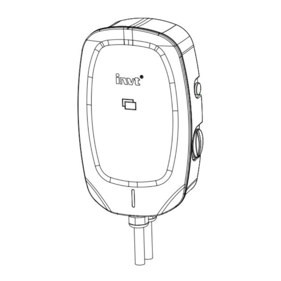
1.8 Product Overview Charger main body cover Front cover plate Emergency stop button Maintenance hole Indicator Manufacturer Logo RFID Reader Mounting hole Rear maintenance cover plate Bottom AC inlet and outlet hole Heat dissipation air inlet Heat dissipation air outlet Note: Heat dissipation fan is only equip on the 22KW charger. - Page 8 Mounting bracket Rear plate Wall installation hole AC wire connector Width of the charger Depth of the charger Height of the charger X: 230 mm Y: 115 mm Z: 375 mm...
-
Page 9: Led Indicators
9 LED indicator Solid Green The charger is on standby / A charging session has ended Green Not illuminated The charger is off Solid Green and Red The charger has a faulty Yellow Solid Yellow and Green The charger is charging the vehicle 2. -
Page 10: Product Technical Parameters
Output characteristics Manufacturer LOGO Protection degree Company name Implementation standards Note: The data in the figure is only a reference and does not represent the physical nameplate of the product. To view the applicable data, find the nameplate on the charger. 2.2 Product technical parameters Electrical parameters Model... - Page 11 over-voltage and under-voltage protection ; Load imbalance protection(only own control core. applies to three-phase five-wire). Input connector 3 Pin terminal 5 Pin terminal Note:8~10 AWG Quantity Charge Note: Length Charging gun wire , total length 5m(including 0.3m) interface Customizable. Type EN IEC 62196-2016 : AC Type 2 Input to Under normal atmospheric pressure , in the environment of relative...
-
Page 12: Preparation For Charger Installation
3. Preparation for charger installation 3.1 General requirements Obtain permission to install this charger in accordance with local regulations The AC power supply is available at the installation position. Make sure cur off the the cable power during installation 3.2. - Page 13 Wiring terminal definition Cable requirement Note: 1. For EVC 16-AW7KGP1UE charger, the maximum continuous working current is 32A, and the cable should meet the above requirements. It is recommended to use the 10 AWG cable with 600Vac withstand voltage. Of course, you can also choose a larger size of the cable. 2.
-
Page 14: Electrical Installation Procedure
2. For EVC 16-AW22KGP1UE Charger, the maximum continuous working current is 32A, and the cable shall meet the above requirements. It is recommended to use a 10 AWG cable with 600Vac withstand voltage. Of course, you can also choose a larger size of the cable. 3. - Page 15 Insert the pre-treated cable into the waterproof jacket. Reserve the cable length around 10~15mm based on the installation position for easy access to the terminal. (Note: Crimp the cable to a tubular terminal is essentially for safety connection ) ...
-
Page 16: Mechanical Installation Of The Charger
Note: 1. In addition to identify the AC input cable connection by above pictures,engineers can also distinguish the wiring by the print on the terminal row. 2. Before connecting the AC input cable to the power grid network, please complete the mechanical installation of the charger first in order to ensure safety. -
Page 17: General Specification
(3) Power distribution module installation Install the module at the side of charger, then insert the current transfer to power input wire L(L1,L2,L3 for three phase) 5.2 General Specification 1. Engineer / user shall provide 4 expansion bolts of M6x50mm and support 10kg. 2. -
Page 18: Support Rear Plate Mounting
5.3 Support rear plate mounting After selecting the installation location , drill the holes on the wall, and the holes aperture should be suitable for the M6 x 50 type expansion bolt. This data can be obtained from the technical parameters of the expansion bolt. Fixing the installation rear plate to the wall with the expansion bolt. -
Page 19: Hanging Ear Installation
5.4 Mounting bracket installation Find out the mounting brackets, fixing screws in the charger package.the installation method like the follow pictures. Installation Schematic diagram of the support hanging ear Charger main body cover Locating pin Mounting bracket M4 x 10 screw 5.5 Installation the whole Charger Install the charger into the rear plate from top to bottom according to the relationship between the mounting bracket and the mounting holes . -
Page 20: Charger Power Supply Operation
Site cleaning: The site debris, garbage and Charger outsourcing boxes shall be discarded in a correct way after the installation, the factory test report, use manual and user RFID card shall be properly kept by the user. 6. Charger power supply operation 6.1 Power on operation Before the Charger is powered on, the following work should be completed. -
Page 21: Power-Off Operation
Schematic Schematic diagram of the diagram of the residual key position of current device the residual closing current device operation 6.3 Power-off operation Carry on the maintenance work of the Charger. Perform charger fault diagnosis. Demolish and scrap the charger and other work. 7. - Page 22 1. Check whether the vehicle load matches the charger. Charger overload 2. Check and connect the charging cables of electric Electric vehicle side overload disconnection vehicles. 3. Correctly connect the electric vehicle charging cable. Input under voltage or Check whether the charger need single phase or three AC power supply not correct Over voltage phase connection.
- Page 23 Fault problem probable cause Possible solutions 1. Check whether the electrical ground cable of the charger is correct. 2. Install the protection ground cable correctly. charger "ground fault" Charger failed to ground properly Install the ground conductor for the power supply network.
Need help?
Do you have a question about the EVC16 Series and is the answer not in the manual?
Questions and answers