Table of Contents
Advertisement
Quick Links
Advertisement
Table of Contents

Related Manuals for ABL Wallbox eM4 Single


Summary of Contents for ABL Wallbox eM4 Single
- Page 1 Wallbox eM4 Single Installation manual Article No.: 0301504_EN_a...
-
Page 2: Contact
Contact ABL GmbH Albert-Büttner-Straße 11 91207 Lauf / Pegnitz Germany +49 (0) 9123 188-0 info@abl.de www.ablmobility.de Customer Service +49 (0) 9123 188-0 www.ablmobility.de/en/service/support/ Contact Revision: 0301504_EN_a Version: 27.10.23... -
Page 3: Table Of Contents
Setup of the Wallbox eM4 Single Configuring the Wallbox eM4 Single Availability of the ABL Configuration App Setting up communication via the ABL Configuration App Onboarding – Configuration of an Extender wallbox for stand-alone operation Onboarding – Configuring the Controller / Extender operating mode... - Page 4 Testing the RCCB Taking the Wallbox eM4 Single out of operation Replacing the RCCB flap Replacing the lever lock in an RCCB flap Replacing the charging socket flap Replacing the housing cover Resetting the wallbox and restoring to factory settings Actions in case of internal errors, notes and warnings Maintenance Appendix Technical specifications...
-
Page 5: Additional Technical Information
It is contained in separate documents. In addition, the technical data for the wallbox are collated in product-specific data sheets. You can download these documents from the ABL website using the following link: https://www.ablmobility.de/en/service/downloads.php NOTE Displaying the additional information on a computer, tablet or smartphone Additional technical information is made available in the Portable Document Format (PDF). -
Page 6: Safety And User Information
Safety and user information General This manual describes all working steps required to install and/or operate the product it concerns. Certain sections of this manual are specially formatted for quick and easy reference. x Descriptions listing equally valid options are indicated by bullet points. 1 Descriptions listing operating steps are numbered in chronological order. - Page 7 Please note that operating a radio transmitter in the immediate vicinity (< 20 cm) of the product may lead to malfunctions. Accessories x It is advisable to only use accessories intended and sold for the product by ABL. x Only use charging cables that comply with the IEC 62196 standard.
-
Page 8: Operating Instructions
Operating instructions x Local safety regulations regarding the operation of electrical devices for the country in which the product is operated always apply. x Ensure that the product can be operated without any strain pulling on its components. x Make sure that the product is always closed and locked when in use. All authorised users must be aware of the 'unlock' position of the key. -
Page 9: Introduction To The Wallbox Em4 Single
Introduction to the Wallbox eM4 Single Thank you for choosing the Wallbox eM4 Single from ABL. The eM4 Single is the ideal solution for efficient vehicle charging in private environments, in public areas and for large group solutions in semi-public company or hotel car parks. In addition to the simple mechan- ical and electrical installation, the ABL Configuration App for mobile devices (iOS, Android) ensures a quick and straightforward setup. -
Page 10: The Wallbox Em4 Single At A Glance
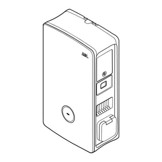
The power module of the Wallbox eM4 Single has a type 2 charging socket for connecting an IEC 62196-1 and IEC 62196-2 certified charging cable, which can be purchased as an accessory from ABL (see “Accessories” on page 19). 7 Wall mounting point The wallbox is fixed in place by screwing it into the wall using the two lower attachment points (see page 28). - Page 11 View from above and below The following illustration shows the top and bottom of the Wallbox eM4 Single. Front Bottom 8 Key opening Insert the supplied key through this opening and push it upwards to open the internal lock on the left-hand side of the housing cover (see also below, RCCB flap ...
-
Page 12: How The Hmi Works
It also includes the RFID reader module for authorising the charging processes, provided that the wallbox was configured accordingly during installation or is operated with a backend. The RFID function is set up via the ABL Configuration App (see “Configuring the Wallbox eM4 Single” on page 35). - Page 13 Factory reset performed When you reset the wallbox to factory settings using the reset button or the help system of the ABL Configuration App (see “Resetting the wallbox and restoring to factory settings” on page 54), the status indicator will light up orange continu- ously.
-
Page 14: Information Displayed In The Energy Meter
If an internal error occurs in the energy meter, the information in the second and third line of the display is replaced by a specific meter error code (example: ). In this case, contact ABL Customer Service (see “Contact” on page 2). Introduction to the Wallbox eM4 Single... -
Page 15: Forming Charging Groups And Network Topologies
Forming charging groups and network topologies The Wallbox eM4 Single offers several interfaces for internal communication in a charging group as well as for external communication with a backend. Here, a distinction is made depending on the wallbox variant: x Controller: The Controller wallbox can be operated either individually or as a charging group together with one or more Extender wallboxes. - Page 16 In the reev ready variants, the SIM card for communication with the reev backend is already pre-installed in the LTE USB stick in the Controller. x LTE communication with the backend must be set up in the ABL Configuration App (see page 35 onwards). x Figure: The Wallbox eM4 Single Controller 1 communicates via the LTE USB stick with an LTE receiver 2, which estab-...
- Page 17 Communication between a Controller and one or more Extenders in a charging group via WLAN x Every Wallbox eM4 Single has an integrated WLAN module. x Direct communication with the ABL Configuration App installed on a smartphone/tablet (iOS, iPadOS, Android) can be estab- lished via the WLAN module.
-
Page 18: External Load Shedding In Accordance With Vde Ar-N 4100
NOTE Compatibility with backend providers The Wallbox eM4 Single is available as a reev ready product, which is specially prepared for operation with the backend solutions from reev. For more information, please visit: https://reev.com x Alternatively, the Wallbox eM4 Single is also compatible with other backends for managing the charging infrastructure. To check the compatibility, please contact the desired backend provider. -
Page 19: Accessories
x Operating manual & safety information x Drilling template, 1 pc. (multilingual), 1 pc. x Folding ferrite with key, for interference suppression in the low-frequency range, 1 pc. The Controller variants of the Wallbox eM4 Single also include: x LTE USB stick for installing an optionally x USB filter for interference suppression available SIM card for communication of data transmission via the LTE USB... - Page 20 = 187 mm, w = 76 mm, d = 105 mm x 100000253 RFID key fobs for all ABL charging stations: Set of ID tag keys (5 pcs.) to extend user pool x 100000193 ABL Energy Meter external meter for integrating the Wallbox eM4 Single Controller(+) into a dynamic load management, top-hat rail module h = 88 mm, w = 70 mm, d = 65 mm...
- Page 21 Pack of 10 individual locks with the same closure, without group key, 10 pcs. x 100000224, […], 100000230 Pack of 10 individual locks with different closures, with one group key, 7 pcs. You can find further information on ABL charging stations and accessories at www. ablmobility.de/en. Accessories...
-
Page 22: Installation Of The Wallbox Em4 Single
Installation of the Wallbox eM4 Single The entire installation of the Wallbox eM4 Single must be carried out by a qualified specialist electrical contractor. DANGER Dangerous electrical currents Electrical installation, as well as final testing and certification for operation must be carried out by a qualified specialist electrical contractor, who, on the basis of their specialist training and experience, as well as their knowledge of the relevant standards, is able to assess and carry out the working steps described in this manual and recognise potential hazards. -
Page 23: Tools And Accessories Required
x Ideally, the installation site should provide a ready connection to the elec- tricity grid. Otherwise, a separate power supply cable must be installed. x In order to operate group installations, suitable data cables must also be installed in the installation site (see also “Inserting the power and data cables”... -
Page 24: Inserting The Power And Data Cables
In addition, you will need the following tools and accessories: x 8 mm drill bit suitable for the x Electric drill respective mounting surface x Pencil x Hammer x Spirit level x Tape measure x Phillips screwdriver x Torx screwdriver (TX 30) x Universal pliers x Utility knife x Stripping tool... -
Page 25: Preparing The Installation Site
Data and control cables The grommets in the inlets for the data cabling within a group (DATA) and for a control cable of the local energy supplier in accordance with VDE AR-N 4100 (EXT. CONTROL) are also designed as “push-out” membranes and can be pierced with the data or control cables. This inlet is intended for a data cable (CAT5 or DATA better) with an RJ45 connector. - Page 26 NOTE Recommended cable lengths for wiring in the wallbox ABL recommends the following cable lengths to ensure problem-free connection in the wallbox: x Power line: at least 130 mm x Data cable: at least 170 mm x Control cable: at least 130 mm...
-
Page 27: Preparing And Fixing The Wallbox In Place
4 Pre-drill the four marked fixing points with the electric drill and drill bit ( 8 mm). 5 Drive the wall plugs into the pre-drilled fixing points with the hammer. 6 Screw the mounting rail into the two upper mounting points using the two TX30 plug screws and the Torx screwdriver. -
Page 28: Electrical Connection Of The Wallbox
NOTE Removing the housing cover To make installation easier, you can remove the housing cover of the wallbox mechanically at any time. This procedure is described in the section “Replacing the housing cover” on page 52. 3 Feed the power line and, if necessary, the data cable into the wallbox through the corresponding grommets in the supply cable area. - Page 29 1-phase connection of the Wallbox eM4 Single If you want to operate the Wallbox eM4 Single in a 1-phase mains system, only connect the L1 supply line to the left-hand termi- nal block (brown). The ends of the unused conductors of the supply line must always be fitted with the supplied insulating caps.
-
Page 30: Phase Rotation Within A Charging Group
DANGER Dangerous electrical currents The electronic components of your wallbox will be damaged if a voltage above 250 V is applied between the L1 current-carrying conductor and neutral! Phase rotation within a charging group To avoid a phase imbalance, the phase rotation must be adjusted according to the following diagram during the electrical installation of the Wallbox eM4 Single: Wiring diagram Wiring diagram... -
Page 31: Connecting A Control Cable In Accordance With Vde Ar-N 4100
3 Fold the communication module back up so that it clicks into place. After establishing the electrical connection of the control cable, the remote disconnection function must be activated via the ABL Configuration App. To do this, please refer to the sections starting on page 39. -
Page 32: Preparing And Installing The Lte Usb Stick
SIM card is provided by the backend provider and must first be inserted in the LTE USB stick. Then plug the LTE USB stick into the USB interface of the Controller and set up the communication via the ABL Configuration App (see page 35 onwards). -
Page 33: Setup Of The Wallbox Em4 Single
Setup of the Wallbox eM4 Single To commission the wallbox, the power supply cable must be connected to the electricity grid. DANGER Dangerous electrical currents The following working steps must be carried out with the utmost care: There is a risk of electric shock if conductive components are touched. - Page 34 6 Use a vehicle simulation adapter to conduct a functional test of the charging function. The mechanical and electrical installation of the Wallbox eM4 Single is now complete and the wallbox can be set up via the ABL Configuration App. NOTE Removing the protective films The housing cover and the window of the energy meter of the Wallbox eM4 Single are covered with films to protect them during...
-
Page 35: Configuring The Wallbox Em4 Single
Updating the software of the charging station, etc. Availability of the ABL Configuration App The ABL Configuration App is offered as an app for mobile devices such as smartphones and tablets. You can download the app for the following operating systems on a mobile device:... - Page 36 Location sharing on Apple devices On iOS 13 / iPadOS 13 and later versions, data for wireless communication can only be accessed if you allow the ABL Configu- ration App to use Location Services on the mobile device. This is a technical policy from Apple, but the location data will not be used by ABL in the app or shared with third parties.
- Page 37 Use the Reset to factory settings option to reset all of the wallbox’s parameters to the factory default. You can then start a new configuration (see below). x The Support option will redirect you to the ABL support website (see “Support via the ABL Support page” on page 45). Extender Wallbox x The button will take you directly to the support website (see “Support via the ABL Support page”...
- Page 38 Updating the software version After the connection is established and during operation, the ABL Configuration App regularly checks whether up-to-date soft- ware is available for the wallbox. If a message to this effect appears, you must install this update before you can continue.
-
Page 39: Onboarding - Configuration Of An Extender Wallbox For Stand-Alone Operation
Configuration of the wallbox by a qualified specialist electrical contractor Before you can start configuring the wallbox, the ABL Configuration App displays a safety warning: The internal parameters of the wallbox may only be changed by a qualified specialist electrical contractor. -
Page 40: Control Board Settings And Reboarding
Control Board settings and reboarding To complete the configuration of the selected operating mode, you can switch to the Control Board of the ABL Configuration App on the last screen. Here you can check all the settings you have made so far and change them if necessary, as well as set up further parameters for operation. - Page 41 Switch the user language of the app between DE, EN, FR, IT and NL after the initial Settings > Language setup. Settings > Help & FAQ Redirects to the ABL support website. Settings > Download configuration Allows you to generate a report of all current settings (charging currents, RFID UIDs, report phase imbalance, etc.) and then send it by email.
-
Page 42: Description Of The Charging Process
Description of the charging process After setting up via the ABL Configuration App, the setup is complete and the Wallbox eM4 Single is ready for charging. We recom- mend carrying out an initial charging process with a vehicle during start-up to ensure the functionality of the wallbox. - Page 43 5 Hold a valid RFID card in front of the status indicator. 6 Check the status indicator and acoustic signals of the wallbox. x If the RFID card has been read successfully, the wallbox emits a short sound signal and checks the authentication of the RFID card.
- Page 44 7 Check the status indicator of the wallbox (display: 1 cycle). x After a request by the vehicle, the charging operation in progress is displayed dynamically via the blue status indicator. x When the charging operation is complete, it is automat- ically terminated by the vehicle, and the status indicator lights up solid blue.
-
Page 45: Error Resolution And Maintenance
To order spare parts, you will need to create a corresponding support ticket in the Service > Support > Spare parts section of the ABL website. In addition to your address data, enter the product number of the spare part and the desired quantity. If you do not know the product number, you can include a product description of the spare part and, if necessary, send a file with additional information (e.g. -
Page 46: Quick Solution For General Problems
Quick solution for general problems In the event of a problem, you do not need to contact ABL Support immediately, as in most cases there is a simple solution. You should therefore always check the following points first before generating a ticket. -
Page 47: Testing The Rccb
Dangerous electrical currents Should the RCCB malfunction during testing, you must not continue to operate the wallbox under any circumstances! x Take the wallbox out of operation (see next section) and contact ABL Customer Service (see “Contact” on page 2). Testing the RCCB... -
Page 48: Taking The Wallbox Em4 Single Out Of Operation
Taking the Wallbox eM4 Single out of operation In case of severe malfunctions or damage to the device, you must take the Wallbox eM4 Single out of operation. To do so, proceed as follows: 1 Unlock the wallbox’s side RCCB flap using the key supplied and flip it up. -
Page 49: Replacing The Rccb Flap
You can replace the side RCCB flap of the power module if it is damaged or otherwise needs to be replaced. Specialist electrical End customer contractor Construction Required components: 100000256 / Spare part eM4 RCCB flap ABL Number / spare part Key for RCCB flap, supplied with the wallbox and the spare part Accessories – Tool Proceed as follows to replace the RCCB flap on the Wallbox eM4 Single:... -
Page 50: Replacing The Lever Lock In An Rccb Flap
NOTE Changing the lock system ABL offers different types of locks for the Wallbox eM4 Single, which can be ordered as accessories (see “Accessories” on page 19). x Locking circuit A: In locking circuit A there are 10 packages to choose from, each with 10 individual locks with the same closure. -
Page 51: Replacing The Charging Socket Flap
4 Loosen the screw for the locking cylinder with a Torx T15 screwdriver. 5 Push the locking cylinder out of the guide of the RCCB flap with the screwdriver. Now proceed in reverse order to install the replacement lock in the RCCB flap. Replacing the charging socket flap You can replace the flap of the Type 2 charging socket if it is damaged or no longer closes reliably. -
Page 52: Replacing The Housing Cover
Specialist electrical End customer contractor Construction Required components: 100000260 / Spare part eM4 SG front ABL Number / spare part Key for RCCB flap, supplied with the wallbox Accessories – Tool... - Page 53 2 Insert the key through the key opening on the bottom left- hand side and push it upwards to unlock the left-hand side of the housing cover. J Open the housing cover to the front. 3 Grasp the housing cover by the two corners in the hinge area and push first one and then the other side backwards with moderate force.
-
Page 54: Resetting The Wallbox And Restoring To Factory Settings
Accessing the help system on an Extender wallbox If you tap the button while the ABL Configuration App is connected to an Extender wallbox, you will be redirected directly to ABL’s support website. Resetting or restoring the wallbox via the reset pushbutton There is a reset pushbutton on the main module of the wallbox which you can use to restart the hardware or reset the wallbox to its factory settings, depending on how long you press the button. -
Page 55: Actions In Case Of Internal Errors, Notes And Warnings
Every malfunction (error, note and warning) is documented in detail ABL Configuration App in the app. If required, you can download a diagnostic report to the mobile device. - Page 56 Contactor / relay does not Charging not possible close x Perform restart by pressing reset push button (< 3 seconds) x Check setting for external load shedding in ABL Configuration App Control by default at terminal Reduced charging current EN1 (note) x Check external control unit (e.g. FNN control box or...
-
Page 57: Maintenance
If the error or warning cannot be remedied or reset by one of the measures described above, switch off the power to the wallbox- (es) for about 2 minutes via the MCB connected upstream in the domestic power distribution. x If the error or warning still cannot be remedied or reset even after doing this, contact ABL Customer Service (see “Contact” on page 2). -
Page 58: Appendix
Appendix Technical specifications eM4 Single Controller series Product number 100000151 Type 4WS-22CNS2 Rated voltage 230 / 400 V Grid frequency 50 Hz Current 32 A Maximum output 1 × 22 kW (3-phase) Charging connection Lockable Type 2 charging socket in acc. with IEC 62196-2 Phase system 3-phase (1-phase connection possible) Direct connection to the terminal block, supply cables up Terminal blocks to a maximum of 10 mm²... - Page 59 Product number 100000151 Dimensions (H × W × D) 516 × 306.5 × 145 mm (W: 290 mm without protrusions) Weight per wallbox Approx. 7.2 kg eM4 Single Extender series Product number 100000157 Type 4WS-22ENS2 Rated voltage 230/400 V Grid frequency 50 Hz Current 32 A Maximum output 1 × 22 kW (3-phase) Charging connection Lockable Type 2 charging socket in acc. with IEC 62196-2 Phase system 3-phase (1-phase connection possible) Direct connection to the terminal block, supply cables up...
-
Page 60: Standards And Guidelines
Product number 100000157 Maximum elevation ≤ 2,000 m AMSL Dimensions (H × W × D) 516 × 306.5 × 145 mm (W: 290 mm without protrusions) Weight per wallbox Approx. 7.2 kg The eM4 Single Controller and eM4 Single Extender wallboxes are also available as variants with shutter charging sockets as well as reev ready versions for operation with the backend solutions from reev. -
Page 61: Overview Of The Radio Modules Used
Overview of the radio modules used Subclass of Class 1 accord- Transmitting Module Band Frequency Frequency range ing to Commission decision power 2000/299/EC RFID 13.56 MHz 13.553 – 13.567 MHz 116 (Spectral mask: I.2) < 10 mW 2100 MHz 1920 – 1980 MHz 1800 MHz 1710 - 1785 MHz 2600 MHz 2500 –... -
Page 62: Definitions
Definitions Abbreviation Explanation Battery Electric Vehicle: Electric vehicle with battery Direct current: Direct current DHCP Dynamic Host Configuration Protocol: Protocol for network communication Electric Mobility Electromagnetic compatibility Electric vehicle: Electric vehicle Frequency Division Duplex: Radio communication technique Network Technology/Network Operation Forum, committee within the VDE GPRS General Packet Radio Service: Service for data transmission in GSM networks General System for Mobile Communications: Mobile communication standard... -
Page 63: Disposal Advice
Copyright and disclaimer Copyright © 2023 Version 0301504_EN_a, Version: 27.10.23 All rights reserved. x Any information contained in this manual may be changed without prior notice and does not represent any obligation on the part of the manufacturer. x Illustrations in this manual may show designs different from the delivered product and do not represent any obligation on the part of the manufacturer. -
Page 64: Ce Certification And Compliance Declaration
The Wallbox eM4 Single carries the CE mark. A copy of the first page of the declaration of compliance is shown below. In addition, you can find a complete digital copy of the declaration of conformity on the ABL website at www.ablmobility.de/en in the section Service >... -
Page 65: Drilling Template Illustration
Drilling template illustration The Wallbox eM4 Single comes with a drilling template (see illustration below) for marking the mounting points and illustrates the basic steps for installation. Should the supplied drilling template have been lost, you can obtain the drilling dimensions from the illus- tration on the front. - Page 66 ABL Configuration App Appendix...
- Page 68 ABL GmbH · Albert-Büttner-Straße 11 · D-91207 Lauf / Pegnitz T. +49 (0) 9123 188-0 · info@abl.de · www.ablmobility.de...
Need help?
Do you have a question about the Wallbox eM4 Single and is the answer not in the manual?
Questions and answers