Table of Contents
Advertisement
Advertisement
Table of Contents

Related Manuals for Ercolina TB100

Summary of Contents for Ercolina TB100
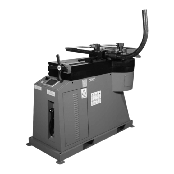
- Page 1 TB100 and TB130 Top Benders Non-Mandrel Pipe, Tube and Profile Bending Machine Operator’s Manual WARNING! BEFORE USE, BE SURE EVERYONE USING THIS MACHINE READS AND THOROUGHLY UNDERSTANDS ALL SAFETY AND OPERATING INSTRUCTIONS IN THIS MANUAL – 1 – 03/2015 TB100/TB130...
-
Page 2: Table Of Contents
CML USA, Inc. Ercolina ® Table of Contents Important safety instructions Special instructions TB100 and TB130 Top Bender features, capacities and specifications Top Bender components Before you begin Standard equipment Wiring instructions and transformer configuration General assembly, machine setup and preparation •... - Page 3 83-84 • Non-mandrel bending troubleshooting • Routine maintenance & grease information • Terms and conditions of sale • Warranty • Ercolina tube, pipe, profile benders and angle rolls 89-90 _____________________________________________________ CML USA Ercolina reserves the right to make improvements and ®...
-
Page 4: Important Safety Instructions
Follow instructions for lubricating and changing accessories. Inspect tool cords periodically and if damaged, have repaired by authorized service facility. Inspect electrical cords periodically and replace if damaged. Keep handles dry and clean and free from oil and grease – 4 – TB100/TB130 03/2015... -
Page 5: Special Instructions
Special Instructions 1. Read and follow operators manual thoroughly. If you require an additional manual please contact CML USA Ercolina at 563-391-7700 or e-mail info@ercolina-usa.com. ® 2. Due to size and weight, it is recommended that qualified professionals transport, position and install bending machine. -
Page 6: Tb100 And Tb130 Top Bender Features, Capacities And Specifications
TB100 and TB130 Top Bender Features ● Ideal for producing consistent quality bends in pipe, tube, squares, solids and other profiles ● Touch screen control offers easy access to auto and manual operating modes, programming (inch or metric), system diagnostics and multiple language capability ●... -
Page 7: Top Bender Components
Top Bender Components Shown below are basic components of a TB100 or TB130 bending machine. Please take a moment to review this illustration for reference. 1. Hand-held control Counterbending die 2. USB for unlimited program storage Hex shaft 3. Touch screen control Center former die 4. -
Page 8: Before You Begin
1. Determine location of machine installation (with machine disconnected from power source). 2. Measure incoming line voltage at power source. Note: the TB100 and TB130 Top Benders utilize an in- verter drive system to deliver power to control board and drive motor. It is highly recommended a proper dedicated circuit is used, failure to do so will result in erratic machine performance. -
Page 9: Powering Machine On
3. Select Services Menu. 4. From Services Menu press RESET button to activate motor & safety circuit. 5. RESET button will illuminate to confirm motor 6. Press HOME button to return to main menu. is on. – 9 – 03/2015 TB100/TB130... -
Page 10: Bending Terminology
Before bending any material you should know the following: 1. Outside and inside physical dimensions 2. Wall thickness 3. ASTM specifications 4. Desired CLR radius 5. Degree of bend 6. Minimum distance between bends 7. Number of bends required per day – 10 – TB100/TB130 03/2015... -
Page 11: Choosing And Installing Hex Shaft
Choosing & Installing Hex Shaft - Install tooling - 1. Install main shaft according to bend die (40, 50, 80). (110) included with TB130 only. No tooling needed – 11 – 03/2015 TB100/TB130... -
Page 12: Installing Center Former And Counterbend Die
- Proper Tooling Selection - Refer to pages 82-84 for recommended centerline bend radius for the material to be bent. If your application requires a CLR or profile that is not shown CML USA Ercolina can quote special tooling on request. As a ®... - Page 13 Counterbending dies are wear items - Replace as necessary to ensure bend quality. Counterbending die should never contact center former when material is in former and tooling is in starting position. - Counterbending die lubrication - For best results counterbending dies should be kept well-lubricated with Ercolina spray grease - #810. ®...
-
Page 14: Loading Workpiece
3. Properly adjusted vise and counterbending die assembly should be perpendicular to workpiece and swing freely counterclockwise to release workpiece (see FIG. 2). Note: If vise assembly pivots away from material at beginning of bend, reduce pressure on vise. Proper counterbending die adjustment ensures satisfactory bends. (FIG. 2) – 14 – TB100/TB130 03/2015... -
Page 15: Axis Explanation
Specification of the axis directions to one another ► - C axis bend angle coordinate system - C axis bend angle is between 0° and 180° – 15 – 03/2015 TB100/TB130... -
Page 16: Referencing "X Axis" Counterbend Die Position
Vise assembly (X axis) positive direction The TB100 and TB130 are equipped with an encoder on the X axis. The encoder displays the position of the X axis which helps maintain consistent and repeatable bends. This encoder can be turned on or off depending on user preference. -
Page 17: Tie Bar
Tie Bar The TB100 and TB130 are equipped with a Tie Bar. It is recommended the tie bar be used at all times. - Mounting tie bar - 1. With tooling mounts and material in position, attach the tie bar eyelet to the top of the hex shaft making sure that the threaded rod rests on the vise mount. -
Page 18: Control Operating Areas
- Set up - Program edit - Refpoint set - MDA mode - Turning on - Load program - Error messages - Save program - Set language - Set unit - Reserved area Operating areas – 18 – TB100/TB130 03/2015... -
Page 19: Manual Mode Without Pressure Die Control
1 - Press the function key MANUAL in the Main menu to display the Manual screen. Manual menu FUNCTION Return to previous menu Go to Manual 1 screen Hand-held control display Axis C current position (degrees) Actual machine load (in %) from 0 to 100% – 19 – 03/2015 TB100/TB130... - Page 20 - After selecting direction, press center of hand-held control to move C axis Note: releasing button stops C motion Note: fully depressing button activates emergency stop C axis positive bending direction C axis negative return direction – 20 – TB100/TB130 03/2015...
- Page 21 1. Select Services Menu. 2. From Services Menu press RESET button to activate motor & safety circuit. 3. RESET button will illuminate to confirm motor 4. Press HOME button to return to main menu. is on. – 21 – 03/2015 TB100/TB130...
- Page 22 Press “NEXT” soft key Following menu appears: Manual 1 menu FUNCTION Decrease speed Increase speed Return to previous menu Speed set up display in % Press BACK and then HOME to return to main menu – 22 – TB100/TB130 03/2015...
-
Page 23: Manual Mode With Pressure Die Control
1 - Press the function key SERVICE in the Main menu to display the Services screen Services menu 2 - Press on PD (pressure die) to move selector to “1” (ON) Press HOME to return to main menu – 23 – 03/2015 TB100/TB130... - Page 24 Manual menu FUNCTION Vise position "0" reset vise position The system displays the vise position in inch or mm according to current service selection Note: Machine will not bend unless this axis is at "0" – 24 – TB100/TB130 03/2015...
- Page 25 - After selecting direction, press center of hand-held control to move C axis Note: releasing button stops C motion Note: fully depressing button activates emergency stop C axis positive bending direction C axis negative return direction – 25 – 03/2015 TB100/TB130...
-
Page 26: Programming (Including Entering And Editing Values)
Functionality: This section describes how to create a new part program or how to modify an existing part program. - Operating sequence - From Main menu Main menu 1 - Select Program menu. The Program main screen appears. Program menu – 26 – TB100/TB130 03/2015... - Page 27 In inch or mm according to selection in service menu. ● Tube Length: In inch or mm according to selection in service menu. FUNCTION Save file on USB Load file from USB Go on next auto page (bending data) Return to main menu – 27 – 03/2015 TB100/TB130...
- Page 28 Use the directional keys to move the cursor within the current value. You can now edit the current value or change the value. Select ENTER to confirm your entry or CLR to cancel them. Both actions close the numeric keyboard. – 28 – TB100/TB130 03/2015...
- Page 29 When you touch an alphanumeric field on the touch screen the following keyboard appears allowing you to give a name or make a comment to a part program. Alphanumeric keyboard Explanation of display elements ELEMENT KEY FUNCTION INPUT FIELD ESCAPE NUMERIC ALPHANUMERIC ENTER SPECIAL CHARACTER BACK SPACE DELETE CLEAR – 29 – 03/2015 TB100/TB130...
- Page 30 For each line (bend), the following parameters can be programmed Angle: Bend angle value in degrees SB: Springback angle in degrees (this value is added to the angle value) It is possible to program 12 bends per program – 30 – TB100/TB130 03/2015...
-
Page 31: Editing A Part Program, Entering Bend Angle
Functionality: This section describes how to modify a part program. Operating sequence From Main menu Main menu 1 - Select “PROGRAM”. The Program main screen appears. Program menu 2 - Select the program number you want to modify then press load from USB. – 31 – 03/2015 TB100/TB130... - Page 32 Springback may be entered now if known. Refer to page 42 (Automatic Mode without pressure die control) or page 50 (Automatic Mode with pressure die control) for instructions on determining springback). When modifications are complete, save data on USB. – 32 – TB100/TB130 03/2015...
-
Page 33: Save A Program On Usb
On the USB the program will be saved with the same edited program number. It is possible also, to change the comment. To change a program comment of a file stored on the USB key, refer to Program List section. – 33 – 03/2015 TB100/TB130... - Page 34 - Program List (files stored on USB) - Functionality: This section describes how to read programs stored on the USB key. Operating sequence From Main menu Main menu 1 - Select “PROGRAM”. The Programming main screen appears. Program menu – 34 – TB100/TB130 03/2015...
-
Page 35: Program List (How To Read Programs Stored On Usb Key)
Use this button to move up in the file list area. Scroll down file list area. Use this button to move down in the file list area. Select file details. Use this button to display details of selected file. – 35 – 03/2015 TB100/TB130... - Page 36 Parameters File list File details - How to display the FILE DETAILS - Operating sequence 1 - Use the soft keys: scroll down or scroll up to display the next or the previous ten programs. – 36 – TB100/TB130 03/2015...
- Page 37 Date is the original date of system, the system does not change the date, you can edit the date and change it manually. Group No: Do not alter Group name: Name associated with program. It may be useful to edit a name or a group name for managing programs. – 37 – 03/2015 TB100/TB130...
-
Page 38: Load A Program From Usb
Press OK button, check the selection, and then try again. b - If the USB key has not been connected, the system will display the following message: Press OK button, connect the USB key, and then try again. – 38 – TB100/TB130 03/2015... -
Page 39: Automatic Mode Without Pressure Die Control
Automatic Mode Without Pressure Die Control - Automatic Mode without pressure die control - - Operating sequences - From Main menu Main menu 1 - Select Automatic menu. The auto main screen appears. Automatic menu – 39 – 03/2015 TB100/TB130... - Page 40 ● DTG: Distance to go for C axis. Hand-held control display In Automatic mode the machine will perform only the program displayed on the screen. To change programs, refer to page 38 of this manual. – 40 – TB100/TB130 03/2015...
-
Page 41: Automatic Menu Selection
1 - From Automatic menu press NEXT. Automatic menu 2 - The Automatic 1 menu screen appears allowing you to change bending speed (%) by using up and down arrows. Note: Load sensor will display actual load of machine.. Automatic menu – 41 – 03/2015 TB100/TB130... -
Page 42: Determining And Entering Proper Springback Value For Bend Angles
- Note actual position - this value is your springback setting Press BACK and then HOME to return to main menu From Main menu Main menu 4 - Select “PROGRAM”. The Program main screen appears. Program menu – 42 – TB100/TB130 03/2015... - Page 43 Original data from current program number i2 displayed. Press “NEXT” to display angle and springback. The following screen appears: Select SB field. Insert new springback setting observed from step "d". Press BACK and then HOME to return to main menu – 43 – 03/2015 TB100/TB130...
- Page 44 From Main menu Main menu 5 - Select Automatic menu. The auto main screen appears. Automatic menu – 44 – TB100/TB130 03/2015...
- Page 45 - After selecting direction, press center of hand-held control to move C axis Note: releasing button stops C motion Note: fully depressing button activates emergency stop C axis positive bending direction C axis negative return direction – 45 – 03/2015 TB100/TB130...
-
Page 46: Automatic Mode With Pressure Die Control
Automatic Mode With Pressure Die Control - Automatic Mode with pressure die control - Operating sequence From Main menu Main menu SERVICES 1 - Press the function key SERVICE in the Main menu to display the Services screen Services menu – 46 – TB100/TB130 03/2015... - Page 47 2 - Press on PD (pressure die) to move selector to “1” Press HOME to return to main menu From Main menu Main menu 4 - Select Automatic menu. The auto main screen appears. Automatic menu – 47 – 03/2015 TB100/TB130...
- Page 48 38 of this manual. Automatic menu When using pressure die encoder in Automatic mode, pressure die position must be set to "0" for machine to operate. To set "0" position press – 48 – TB100/TB130 03/2015...
-
Page 49: Automatic Menu Selection
1 - From Automatic menu press NEXT. Automatic menu 2 - The Automatic 1 menu screen appears allowing you to change bending speed (%) by using up and down arrows. Note: Load sensor will display actual load of machine. Automatic menu – 49 – 03/2015 TB100/TB130... -
Page 50: Determining And Entering Proper Springback Value For Bend Angles
- Note actual position - this value is your springback setting Press BACK and then HOME to return to main menu From Main menu Main menu 4 - Select “PROGRAM”. The Program main screen appears. Program menu – 50 – TB100/TB130 03/2015... - Page 51 Original data from current program number id displayed. Press “NEXT” to display angle and springback. The following screen appears: Select SB field. Insert new springback setting observed from step "d". Press BACK and then HOME to return to main menu – 51 – 03/2015 TB100/TB130...
- Page 52 From Main menu Main menu 5 - Select Automatic menu. The auto main screen appears. Automatic menu – 52 – TB100/TB130 03/2015...
- Page 53 - After selecting direction, press center of hand-held control to move C axis Note: releasing button stops C motion Note: fully depressing button activates emergency stop C axis positive bending direction C axis negative return direction – 53 – 03/2015 TB100/TB130...
-
Page 54: Mda Mode
3 - On the Cycle C program value enter desired value. 4 - On C springback value enter desired value. Note: The programmed cycle will run using actual parameters displayed. The parameters of the program are actually displayed on the Auto page. – 54 – TB100/TB130 03/2015... -
Page 55: Services
From Main menu Main menu SERVICES 1 - Press the function key SERVICE in the Main menu to display the Services screen. Services menu Press button to switch unit. (inches / mm) Return to main menu. – 55 – 03/2015 TB100/TB130... -
Page 56: Alarm List Display And Overview
Press one time to switch on; press again to switch off Brake test - press to release motor break (You should be able to hear break noise) Press to display alarm list (current alarms displayed – 56 – TB100/TB130 03/2015... - Page 57 OVERLOAD SPEED An overload in C axis is detected, Move C axis in opposite REDUCTION the system automatically reduced direction (-) the speed MOTOR OVER C axis motor too hot Wait until the alarm disappears TEMPERATURE – 57 – 03/2015 TB100/TB130...
-
Page 58: Changing Language
1 - Press the function key SERVICE in the Main menu to display the Services screen. Press next for language selection. Selection: Edit value and insert number corresponding with desired language. Return to previous menu. – 58 – TB100/TB130 03/2015... -
Page 59: Accessing Protected Area
From Main menu Main menu Services menu SERVICES 1 - Press the function key SERVICE in the Main menu to display the Services screen. Press next for language selection. Press to access protected area (password required). – 59 – 03/2015 TB100/TB130... -
Page 60: Referencing "C Axis" Position
Factory set “C axis” position May vary according to tooling design 1 - From Main Menu Screen press the TOOLS icon. 2 - From Services Menu press NEXT icon two times to advance to MD RESTORE screen. – 60 – TB100/TB130 03/2015... - Page 61 EXIT 4 - Press the EXIT key to return to the Main menu TB100- TB130 Note : If you press the central button of the joystick to the maximum pressure the machine will switch to emergency mode . You can reset the EMERGENCY status with the rotation of the emergency button and push the reset button.
-
Page 62: Grounding And Wiring Schematics
– 62 – TB100/TB130 03/2015... - Page 63 – 63 – 03/2015 TB100/TB130...
- Page 64 – 64 – TB100/TB130 03/2015...
- Page 65 – 65 – 03/2015 TB100/TB130...
- Page 66 – 66 – TB100/TB130 03/2015...
- Page 67 – 67 – 03/2015 TB100/TB130...
- Page 68 – 68 – TB100/TB130 03/2015...
- Page 69 – 69 – 03/2015 TB100/TB130...
- Page 70 – 70 – TB100/TB130 03/2015...
- Page 71 – 71 – 03/2015 TB100/TB130...
- Page 72 – 72 – TB100/TB130 03/2015...
- Page 73 – 73 – 03/2015 TB100/TB130...
-
Page 74: Electrical Parts List
2966171 Relay PLC-RSC-24DC/21 803595 Safety module ZBFM 5/WH:UNBEDRUCKT 3040290 Plug ST-COMBI SP2,5/5 5P 3040355 Plug ST-COMBI SP2,5/11 11P 107-3728 RESISTANCE 250R CONT.ALL.10W KA4- 3RT1017- 1BB42 Contactor .SIEM.5,5K2 24VDC TP109 Cable “IN”AUTOTRASF.TRIFASE 030 TP109A Cable “OUT”AITPTRASF.TRIFASE030 – 74 – TB100/TB130 03/2015... - Page 75 VS-04-BUA-BUB-F/IP67 USA A-B plug 1652606 VS-08-SD-F Protection cover IP67 458-1654 USBcable A-B 0,8MT USB-STICK USB-STICK RE 2GB PQI P518C1 Power supply cable 050 without plug P517 Grommet 7-12 PG13,5 Cod. 3246 P517A GHIERA C/DADO PG13,5 Cod.86624 – 75 – 03/2015 TB100/TB130...
- Page 76 Liv. 0 Liv. 1 Description Options Machine 230V TP024AT/2 A.TRANSF. V190-200-230-260 VU230 Machine 400V TP024AT/1 A.TRANSF. V360-400-440-480 VU230 Machine 415V TP024AT/4 A.TRANSF. V360-400-415-440 VU230 Machine 445V TP024AT/5 A.TRANSF. V400-415-430-445 VU230 Machine 507V TP024AT/3 A.TRANSF. V500-550-575-600 VU230 – 76 – TB100/TB130 03/2015...
-
Page 77: Gear Case Schematic
– 77 – 03/2015 TB100/TB130... - Page 78 – 78 – TB100/TB130 03/2015...
-
Page 79: Material Length Required For Rotary Bends In Pipe (Tube And Pipe Information)
.109 .140 .191 .250 .382 1½ 1.900 .065 .109 .145 .200 .281 .400 2.375 .065 .109 .154 .218 .344 .436 2½ 2.875 .083 .120 .203 .276 .375 .552 3.500 .083 .120 .216 .300 .438 .600 – 79 – 03/2015 TB100/TB130... -
Page 80: Conversion Tables - Mm To Inches And Inches To Mm
– 80 – TB100/TB130 03/2015... -
Page 81: Minimum Distance Between Bends By Center Line Radius, Pipe And Tube Kits
5.708 5.905 6.692 5.905 7.283 5.905 7.480 5.905 8.858 5.905 10.236 6.299 11.811 6.299 TB100 with Pipe Kit • Part# TB100P TB130 with Pipe Kit • Part# TB130P Pipe Min. Center Former Counterbend Die Size Wall Part # Part # 1¼″... -
Page 82: Tooling For Pipe
110mm 157R350P400-110 152BP4000 80mm and 110mm drive diameters available for TB100 and TB130 All standard Ercolina counterbending dies are provided in bronze. *Part# 050E required when bending radii 225mm and larger. (Not required for TB100/TB130/TB180.) – 82 – TB100/TB130 03/2015... -
Page 83: Tooling For Tube
.035 156R170T1500 .035 153R190T1500 .109 153R090T1625 .083 153R100T1625 .065 50mm 153R130T1625 1⅝″ 1.625 154T1625 .049 153R150T1625 .035 156R170T1625 .035 153R190T1625 .109 153R100T1750 1¾″ 1.750 .095 153R130T1750 154T1750 .095 153R150T1750 - Continued on next page - – 83 – 03/2015 TB100/TB130... - Page 84 3.500 .216 155P3000 13.8 157R350P3000-80 4″ 4.000 .216 13.8 110mm 157R350T400-110 152BT4000 80mm and 110mm drive diameters available for TB100 and TB130 *Part# 050E required when bending radii 225mm and larger. (Not required for TB100/TB130/TB180.) – 84 – TB100/TB130 03/2015...
-
Page 85: Non-Mandrel Bending Troubleshooting
(plus and minus) button on control pad to adjust display to actual voltage. Die wears prematurely Too much pressure, not enough lubricant Decrease pressure and use lubricant – 85 – 03/2015 TB100/TB130... -
Page 86: Routine Maintenance & Grease Information
Grease fittings are permanently installed by a threaded connection leaving a connection that a grease gun attaches to. To prolong the life of your Ercolina bending machine it is important to grease the zerks (fittings) every 40 work hours or 1,000 bends. WD-40 and other penetrating oils actually break down the grease and can cause damage to your machine. -
Page 87: Terms And Conditions Of Sale
13. Limitations for Suits. Any cause of action or claim arising out of or relating to CML’s performance or failure to perform hereunder or the furnishing, performance, or use of the Goods hereunder must be commenced within one (1) year after the claim or cause of action has accrued. T&C_01-2014 – 87 – 03/2015 TB100/TB130... -
Page 88: Warranty
Goods to Seller at Seller’s direction and expense. No Goods are to be returned to Seller without Seller’s prior written consent. THE REMEDIES SET FORTH HEREUNDER SHALL CONSTITUTE THE EXCLUSIVE REMEDIES AVAILABLE TO BUYER AND ARE IN LIEU OF ALL OTHER REMEDIES. Warranty_01-2014 – 88 – TB100/TB130 03/2015...
Need help?
Do you have a question about the TB100 and is the answer not in the manual?
Questions and answers