
Related Manuals for ATECH BC 900


Summary of Contents for ATECH BC 900
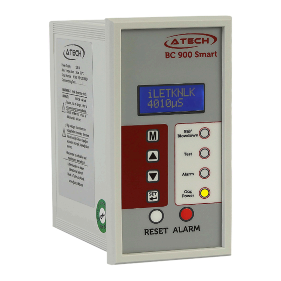
- Page 1 BC 900 SMART TDS BLOWDOWN CONTROLLER Installation and Operating Instructions Smart Automatic TDS Blowdown Controller BC 900 IM-BC900-18C www.atech-ltd.com...
-
Page 2: Table Of Contents
5.2.13 Software Version 6. START UP 7. MAINTENANCE ATECH ENDÜSTRİYEL ÜRÜNLER SAN. VE TİC. LTD. ŞTİ. Giyim Kent 16. Sok. No: 79 Esenler/İstanbul - Turkey P : 0.212.438 42 38 F: 0.212.438 42 58 E : servis@atech-ltd.com W : www.atech-ltd.com IM-BC900-18C www.atech-ltd.com... -
Page 3: Safety Informations
BC 900 SMART TDS BLOWDOWN CONTROLLER 1. SAFETY INFORMATIONS Safety! Installation, commissioning and maintenance of this device must be done by a qualified person in compliance with the operating instructions. Otherwise device and related equipments may be damaged and personnel may be injured. -
Page 4: Description & Functions
2.1 Typical applications - BCS 950 & BCS 930 Automatic TDS Blowdown Systems Smart Automatic TDS Blowdown Controller BC 900, detects the electrical conductivity (TDS - Total Dissolved Solids) of boiler water via the Conductivity Probe CP 950 or CP 930. - Page 5 SMART TDS BLOWDOWN CONTROLLER 2.2 Typical applications - BCS 920 Automatic TDS Blowdown Systems Smart Automatic TDS Blowdown Controller BC 900, detects the electrical conductivity (TDS - Total Dissolved Solids) of boiler water via the Conductivity Probe CP 920. The TDS Blowdown Control Valve BCV 915 opens and closes in response to a high TDS signal from Smart Automatic TDS Blowdown Controller BC 900.
-
Page 6: Technical Specifications
Allow 20 mm minimum clearance all round the unit for air circulation. Figure 3 Panel cut out dimensions of Smart Bottom Blowdown Controller BC 900 Please refer to "BCV 900 Installation and Operation Manual for Automatic TDS Blowdown Control Valve" and "CP 920, CP 930 or CP 950 Installation and Operation Manual for Conductivity Probe"... -
Page 7: Wiring
Otherwise, this could cause damage to equipment and even damage to people. Wiring for BCS 950 & BCS 930 Automatic TDS Blowdown Systems Figure 4 TDS Blowdown Controller BC 900 electrical connection diagram for BCS 950 & BCS 930 Blowdown Systems Wiring for BCS 920 Automatic TDS Blowdown Systems Figure 5 TDS Blowdown Controller BC 900 electrical connection diagram for BCS 920 Blowdown Systems Note: Relays shown in de-energised state. - Page 8 Figure 6 Wiring for CP 920 Conductivity Probe and TP 900 Temperature Probe at BC 900 TDS Blowdown Controller Blue and Red cables at CP 920 Conductivity Probe, shoud be connectted to the BC 900 TDS Blowdown Controller as three cables thanks to a junction box as showed at Figure 6. Red cables must be connected to therminals 1 and 2, Also blue cable must be connected to terminal 3 at BC 900 TDS Blowdownd Controller.
-
Page 9: Display Definitions And Button Functions
BC 900 SMART TDS BLOWDOWN CONTROLLER 5. FUNCTION AND CONFIGURATIONS 5.1 Display Definitions and Button Functions. LCD Screen Enter or return to main menu Blowdown Led Scroll up menus and increase digits Test Led Scroll down menus and Alarm Led... -
Page 10: Startup Screen
Then conductivty value, will be seen on the screen of the conrtroller 5.2.2 Enter Commissioning Hold down button for 5 seconds to enter commissioning mode. To obstruct unauthorized interferences, BC 900 has password protection. buttons change each digit and button passes the next digit. After change the last digit, button accepts the password and if it is true, it automatically enters the main menu. -
Page 11: Hysteresis Set
TDS drops below the hysteresis of the SP. It can be selected 5% of set conductivity value. 5.2.5 Alarm Set Smart Blowdownd Controller BC 900 provides alarm relay output when conductivity level gets over the value adjusted with this function. Alarm relay released at this TDS level. -
Page 12: System Mode Auto/Off
BC 900 SMART TDS BLOWDOWN CONTROLLER 5.2.8 System Auto / Off In this mode can be setted as "System Run" that gives An automatic blowdown or "System Off" that the timer will give no blowdown. "System Auto" This mode gives an automatic blowdown, and is the usual mode selected. -
Page 13: Modbus Setup
BC 900 SMART TDS BLOWDOWN CONTROLLER 5.2.10 Modbus Setup (Optional) This function is used to set Modbus address baud rate and infrared master/slave configuration, and verifies the number of units on the IR bus 5.2.11 Password This function is used to change the password of the device. -
Page 14: Software Version
Allows the software version to be viewed. 6. COMMISSIONING • Be sure that all phase and neutral ends are connected to the right terminals on BC 900 Smart Automatic Bottom Blowdown Controller before energyz. • Be sure that all function values are adjusted correctly. - Page 15 BC 900 SMART TDS BLOWDOWN CONTROLLER IM-BC900-18C www.atech-ltd.com Page 15...
- Page 16 BC 900 SMART TDS BLOWDOWN CONTROLLER ATECH ENDÜSTRİYEL ÜRÜNLER SAN. VE TİC. LTD. ŞTİ. Giyim Kent 16. Sok. No: 79 Esenler/İstanbul - Turkey P : +.90.212.438 42 38 F: +.90.212.438 42 58 E : servis@atech-ltd.com W : www.atech-ltd.com IM-BC900-18C www.atech-ltd.com...
Need help?
Do you have a question about the BC 900 and is the answer not in the manual?
Questions and answers