Table of Contents
Advertisement
Advertisement
Table of Contents
Troubleshooting

Summary of Contents for Scanreco G6
- Page 1 Service Manual G6 Radio Remote Control System...
- Page 2 No part of this document may be reproduced or transmitted in any form or by any means, electronic or mechanical including photocopying, recording, storage in an information retrieval system, or otherwise, without the prior written permission of Scanreco AB, Sweden. Document Information:...
-
Page 3: Table Of Contents
Scanreco – Service Manual G6 Radio Remote Control System Table of Content Disclaimer ....................6 Symbols .....................6 Glossary .....................7 PART 1: TECHNICAL INFORMATION ................ 9 Introduction ..................... 9 1.1. Scanreco Integrated Safety Platform (SISP )..........9 1.2. Product Labels ...................9 1.2.1. Transmitter Product Labels ...............10 1.2.2. - Page 4 Scanreco – Service Manual G6 Radio Remote Control System 6.2. Receiver Installation ..................30 6.2.1. Antenna ....................33 6.3. Transmitter Setup ..................33 6.3.1. Initial Pairing .....................33 6.3.2. Color Display Setup .................. 34 6.4. Bluetooth Connectivity ................35 6.5. Battery Charger ..................35 6.5.1. Battery Charger Safety Information ............36 6.5.2.
- Page 5 Scanreco – Service Manual G6 Radio Remote Control System PART 3: APPENDIX 1 – G6 CANOPEN SPECIFICATION ........... 1 Protocol ....................1 1.1. General Settings ..................1 1.2. NMT ......................1 1.3. SDO ......................2 1.4. PDO Configuration ..................2 1.5. LSS ......................2 SRDO ....................... 2 2.1.
-
Page 6: Disclaimer
THE CONTENT OF THIS DOCUMENT ARE SUBJECT TO REVISION WITHOUT NOTICE DUE TO CONTINUED PROGRESS IN DESIGN, EQUIPMENT, TECHNICAL DATA, AND MANUFACTURING. SCANRECO SHALL HAVE NO LIABILITY FOR ANY DEATH, INJURY, DAMAGE OR ERROR OF ANY KIND RESULTING FROM THE BREACH OF, OR NON-COMPLIANCE WITH, THIS DOCUMENT. -
Page 7: Glossary
Scanreco – Service Manual G6 Radio Remote Control System Glossary Term Description Actuator Joystick, lever, toggle switch, push button, and potentiometer Analog Digital Converter Bluetooth Low Energy CAN bus Controller Area Network Cyclic Redundancy Check Control Unit (Receiver) EEPROM Electrically Erasable Programmable Read-only Memory... - Page 8 Scanreco – Service Manual G6 Radio Remote Control System – 8 –...
-
Page 9: Part 1: Technical Information
PART 1: TECHNICAL INFORMATION Introduction The G6 Micro or Mini transmitter together with a G6 CAN receiver makes a complete Scanreco G6 radio remote control system. This system has been developed for professional usage in various safety critical applications in construction and industrial settings. The Scanreco G6 radio remote control system offers numerous configuration possibilities to suit different machines and operator preferences. -
Page 10: Transmitter Product Labels
Scanreco – Service Manual G6 Radio Remote Control System 1.2.1. Transmitter Product Labels Transmitter Product Label Transmitter Warning Label 1.2.2. Receiver Product Labels Receiver Product Label Receiver Radio Label Receiver General Label – 10 –... -
Page 11: Safety Instructions
• It is the machine manufacturer and system installer's responsibility to label machines and products for the safe and reliable use and control of the machine with the Scanreco G6 radio remote control system. • Make sure that only qualified, approved, and competent personnel carry out the installation and maintenance of the products. -
Page 12: Safety Precautions For Operation
Scanreco – Service Manual G6 Radio Remote Control System Safety Precautions for Operation It is the responsibillity of the system installer or machine producer to forward these safety warnings to the machine owner and operator. WARNING! • Make sure that all the warnings in the user manual is permanently available to all machine operators. -
Page 13: External System Overview
Scanreco – Service Manual G6 Radio Remote Control System External System Overview These are the main components of the G6 radio remote control system: 1. Transmitter. 2. Receiver. 3. Battery charger. 4. Battery. (4x) RoHS compliant RoHS compliant Volym Där ej annat anges Filnamn Ersätter... -
Page 14: Transmitters Overview
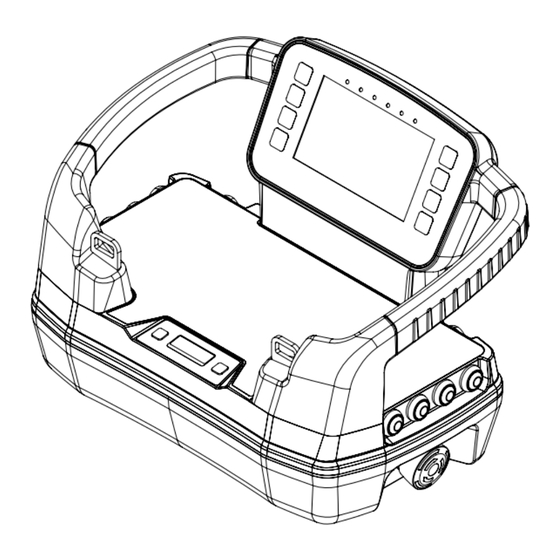
Scanreco – Service Manual G6 Radio Remote Control System 3.1. Transmitters Overview Micro Transmitter Views 170 mm RoHS compliant 6.7 inches Volym Där ej annat anges Filnamn Ersätter ISO 2768-m Volume Where not specified File Name Replacing RoHS compliant Ritad av... - Page 15 Scanreco – Service Manual G6 Radio Remote Control System Mini Transmitter Views 194 mm RoHS compliant 7.6 inches Volym Där ej annat anges Filnamn Ersätter ISO 2768-m Volume Where not specified File Name Replacing Vikt Skala Ritad av Godk. Dwn By...
-
Page 16: Receiver Overview
Scanreco – Service Manual G6 Radio Remote Control System 3.2. Receiver Overview Receiver Views (4x) 49 mm 1.9 inches 118 mm 9.6 inches ISO View Side View (Left) 1. AMPSEAL connector 2. Magnet symbol (for pairing) 3. Product label (Located on left and right side) 4. -
Page 17: Battery And Battery Charger Overview
Scanreco – Service Manual G6 Radio Remote Control System 3.3. Battery and Battery Charger Overview NiMH Battery 74 mm 2.9 inches ISO View Top View Bottom View 1. Poles 3. Product label 2. Mechanical stop 28 mm 1.1 inches Side View... - Page 18 Scanreco – Service Manual G6 Radio Remote Control System Li-ion Battery 74 mm 2.9 inches ISO View Top View Bottom View 1. Mechanical stop 3. Product label 2. Poles 28 mm 1.1 inches Side View Li-ion Battery Battery Charger Ytbehandling Ytjämnhet...
-
Page 19: Technical Description
Scanreco – Service Manual G6 Radio Remote Control System Technical Description 4.1. Transmitters and Receiver Specifications NOTICE! The information below may differ in OEM customized systems. For more detailed information regarding your system setup, see separate technical documentation. Technical data... -
Page 20: Color Display Specifications
The color display runs on a Linux computer with a Qt graphic programming environment. To program the color display, you need programming knowledge in C and Qt. For further information about Qt, see www.qt.io. Contact your point of purchase or Scanreco for instructions about programming the color display. -
Page 21: Color Display Wi-Fi Specifications
Scanreco – Service Manual G6 Radio Remote Control System Technical data Color Display Color Display Color Display Standard Premium Basic Premium Full Size 4.3" 4.3" 4.3" Resolution 480 x 272 pixels 480 x 272 pixels 480 x 272 pixels Buttons... -
Page 22: Transmitter Main Board
Scanreco – Service Manual G6 Radio Remote Control System 4.3. Transmitter Main Board K820 K900 K901 K902 K903 K821 SDI 1 – 4 Encoder DI 1 – 12 DI 13 – 24 DI 25 – 36 SDI 5 – 8... - Page 23 Scanreco – Service Manual G6 Radio Remote Control System Connector Name Description K1000 LED 1-8 LED output (9 pole connector) Pin 1 LED 1 K1001 LED 9-16 Pin 8 LED 8 Pin 9 +5 V Common anode K801 AI 1 Analog input 1 for safety actuator.
- Page 24 Scanreco – Service Manual G6 Radio Remote Control System K1302 K300 K301 BC–EXP DISPLAY RANGECTL K302 K1301 K1300 K200 K201 STOP K1002 K1004 K1003 K1005 K1006 K912 K303 InfoCenter K911 K910 DI 41-44 DI 37-40 Component side Connector Name Description...
- Page 25 Scanreco – Service Manual G6 Radio Remote Control System K300 Display Connect all G6 compatible Displays K200 BOTTOMCONN Bottom part interface (10 pole connector) Pin 1 CAN H signal Pin 2 CAN L signal Pin 3 Pin 4 Battery 2 communication...
-
Page 26: Standard And Optional Features
Scanreco – Service Manual G6 Radio Remote Control System Standard and Optional Features 5.1. Standard Features 5.1.1. Information Center Display The information center is a small display on the top section, located next to the customizable area. The main purpose of the information center is to give the operator essential information about the transmitter's operating status. -
Page 27: Haptic Feedback
Scanreco – Service Manual G6 Radio Remote Control System 5.2.2. Cable Control The cable control functionality is always built into the receiver but optional for the transmitters and requires an external connector. The standard length of the tether cable is 10 meters. The cable control is used: •... -
Page 28: Part 2: Installation, Troubleshooting And Maintenance
Scanreco does not take responsibility for any damage or injury caused by inadequate safety implementations. • If the G6 system is used in a safety critical application, the system installer must do the appro- priate testing and analysis of the final application to prevent injury to the end user. NOTICE! The radio and cable communication protocols in G6 are different from other Scanreco platforms. -
Page 29: Manual Mode
Scanreco – Service Manual G6 Radio Remote Control System • STOP output: The STOP output is permanently high when the STOP button is in released state, the transmitter is switched on and a radio link is established. For some system configurations there are certain startup criteria that require fixed toggles and rotary potentiometers to be in zero-position before the STOP output can go high. -
Page 30: Receiver Pinout
Scanreco – Service Manual G6 Radio Remote Control System 6.1.5. Receiver Pinout 14-Pin AMPSEAL Signal Description VIN REMOTE Power supply 12/24 VDC (Absolute maximum ratings 9-36 VDC) (Use external fuse 10 A) LOOP IN Safety classified loop input 9-36 VDC. Closed when transmitter is switched on and radio link established. - Page 31 Scanreco – Service Manual G6 Radio Remote Control System 4. Install the Receiver vertically or horizontally with the cable connections downwards or Ytbehandling Ytjämnhet Material Surface Treatment Surface Finish Material Volym Filnamn Där ej annat anges Ersätter ISO 2768-m CU14pAnt_dummy for manuals...
- Page 32 Africa: 433 MHz The list above is a simplified overview. Country specific differences occur. If you are uncertain about which frequency and output power to use, contact your point of purchase or Scanreco for further support. WARNING! External components connected to the receiver must have electrical safety approvals and fire enclo- sures if needed.
-
Page 33: Antenna
Scanreco – Service Manual G6 Radio Remote Control System 6.2.1. Antenna The receiver has an external antenna that is connected to the receiver with a RP-SMA connector. If the antenna needs replacing, make sure to use an antenna for the matching frequency (Maximum gain is 2 dBi for 2.4 GHz and +1 dBi for 868/915 MHz). -
Page 34: Color Display Setup
Scanreco – Service Manual G6 Radio Remote Control System 7. When the receiver is found its serial number will show on the 24678943 information center. 8. Make sure the serial number seen in the information center matches the intended receivers' serial number found on the product label. -
Page 35: Bluetooth Connectivity
Scanreco – Service Manual G6 Radio Remote Control System 6. Switch on the transmitter. a. A green icon will show when the graphics are being uploaded to the display. b. A message will be shown when the upload is finished. -
Page 36: Battery Charger Safety Information
Scanreco – Service Manual G6 Radio Remote Control System 6.5.1. Battery Charger Safety Information CAUTION! • This appliance is not intended for use by persons (including children) with reduced physical, sensory, or mental capabilities, or lack of experience and knowledge, unless they have been given supervision or instruction concerning use of the appliance by a person responsible for their safety. -
Page 37: Battery Charger Installation
Scanreco – Service Manual G6 Radio Remote Control System 6.5.2. Battery Charger Installation STEP 1: Connect the power cable. 1. Connect power cable to DC connector. 2. Place the power cable in the cable track to prevent it from disconnecting. -
Page 38: Troubleshooting
The information center on the transmitter will light up in RED when a system error has occurred in any part of the Scanreco G6 radio remote control system. A four-digit error code will be shown on the display along with a warning triangle. If there are multiple errors the error codes will be shown cyclical. - Page 39 Scanreco – Service Manual G6 Radio Remote Control System Code Cause of error Possible reason Correction 1001 The dual electrical signals Faulty stop button or main Repair or replace the transmit- from the stop button have board error. ter if the stop button is pressed...
- Page 40 Scanreco – Service Manual G6 Radio Remote Control System Code Cause of error Possible reason Correction 1701 – 1702 The 5V reference voltage for Main board error. Replace the main board or correct operation of the actua- transmitter tors have failed.
- Page 41 Scanreco – Service Manual G6 Radio Remote Control System Code Cause of error Possible reason Correction 2008 / 2208 A CRC error has been found in Application software error. Replace the main board and / or the communication protocol. reprogram the application External EMC interference.
- Page 42 Scanreco – Service Manual G6 Radio Remote Control System Code Cause of error Possible reason Correction 2023 / 2223 Reading cycle sampling error Application software error. Replace the main board and / or for safety classified inputs. reprogram the application Hardware error.
- Page 43 Scanreco – Service Manual G6 Radio Remote Control System Code Cause of error Possible reason Correction 2108 / 2308 A feedback signal for safety Hardware error. Replace the receiver if the classified outputs indicates error continues. External EMC interference. that the output is on when it should be off.
- Page 44 Scanreco – Service Manual G6 Radio Remote Control System Code Cause of error Possible reason Correction 2123 / 2323 Power supply has been found Incorrect wiring. Make sure the power is sup- on both manual and remote plied to only one input at any Hardware error.
- Page 45 Scanreco – Service Manual G6 Radio Remote Control System Code Cause of error Possible reason Correction 8104 A CAN PDO length error has Incorrect RPDO length is Make sure the object occurred in CAN1 received. dictionary is reset. Make sure that the correct length on the RPDO is accurate.
-
Page 46: Self-Test Mode
Scanreco – Service Manual G6 Radio Remote Control System Code Cause of error Possible reason Correction 9504 The receiver application was No hardware support for RTC. Make sure that the receiver is unable to read time and date equipped with RTC. Disable Hardware error. - Page 47 Scanreco – Service Manual G6 Radio Remote Control System How to use Self-test mode: 1. Press the two buttons next to the information center display, Next (left side) and Confirm (right side), at the same time. 2. Press the Next button to navigate between options in the information center menu.
-
Page 48: Analog Actuators
Scanreco – Service Manual G6 Radio Remote Control System 7.2.1. Analog Actuators The analog actuators are joysticks, levers, and potentiometers. A set of numbers will show on the display when the Analog actuator self-test is started. The numbers shown on the display refer to: 1. -
Page 49: Digital Actuators
Scanreco – Service Manual G6 Radio Remote Control System 7.2.2. Digital Actuators The digital actuators are push buttons, toggle switches and rotary switches. A set of numbers will show on the display when the Digital actuator self-test is started. The numbers shown on the display refer to: 1. -
Page 50: Rotary Encoders
Scanreco – Service Manual G6 Radio Remote Control System 7.2.3. Rotary Encoders A maximum of three rotary encoders can be configured on the transmitter. A set of numbers will show on the display when the Rotary encoders self-test is started. Check the status of the rotary encoders by turning them individually in increments of one (1) between the minimum and maximum values (000-255). -
Page 51: Pitch And Roll Angle Of Transmitter
Scanreco – Service Manual G6 Radio Remote Control System 7.2.4. Pitch and Roll Angle of Transmitter The transmitter can be configured with a tilt-sensor that measures the tilt of the transmitter in the x- and y-directions. A set of numbers will show on the display when the Pitch and roll angle self-test is started. -
Page 52: Status Indications
Scanreco – Service Manual G6 Radio Remote Control System 7.3. Status Indications 7.3.1. Receiver Status Indications The Receiver is equipped with one LED that indicates status for errors, pairing and connection. The LED will light up in three different colors:... -
Page 53: Battery And Charger Status Indications
Scanreco – Service Manual G6 Radio Remote Control System 7.3.3 Battery and Charger Status Indications Symbols will be visible on the main screen of the Information center display that indicates the status of the batteries' charge and the batteries' condition. If the transmitter has two battery compartments, two status symbols will be visible, one for each battery. -
Page 54: Lock Status
Scanreco – Service Manual G6 Radio Remote Control System 7.3.4. Lock Status If the transmitter is locked, the lock symbol will be visible on the information center display. When locked, the transmitter will not be able to link up to a receiver. The button combination presented below is used to both lock and unlock the Transmitter. -
Page 55: Radio Signal
Scanreco – Service Manual G6 Radio Remote Control System 7.3.6. Radio Signal The current state of the transmitter's radio signal strength will be visible on the main screen of the information center. The different radio signal states will be indicated by radio signal bars. -
Page 56: Maintenance
8.1. System Level 8.1.1. Modulate Modulate is a Windows software and digital servicing tool developed by Scanreco that allows you to: • Connect to the transmitter or receiver via Bluetooth Low Energy (BLE). • View and clear error codes. -
Page 57: Software Version
Contact your point of purchase or Scanreco for support regarding parameters and Modulate. 8.1.1.1. Software Version The software version is available through the Scanreco digital servicing tool Modulate. To identify the software programmed into the product the G6 software version follows a strict naming convention. Naming convention: <Family>-<Type of Unit>-<Customer>-<Version>-<GIT commit>-<GIT hash>-[Dirty]-<Type of software>... -
Page 58: Spare Parts
Scanreco – Service Manual G6 Radio Remote Control System 8.1.2. Spare Parts Available spare parts are presented in alphabetical order in the table below. • Spare parts list meanings: P00027-Cxxxxxxx00: This item number refers to the specific customer configuration. See the product label for your specific configuration number. Replace “xxxxxxx” with the configuration number found on the product label. - Page 59 Carrying Neck Strap Black Accessory Operator 48063 Carrying Vest Orange Accessory Operator 102521_S CU CAN G6 2.4 GHz (General spare part that needs Receiver Service Point programming via Modulate) 102520_S CU CAN G6 868/915 MHz/2.4 GHz (General spare part Receiver Service Point...
- Page 60 Scanreco – Service Manual G6 Radio Remote Control System Item number Description Product Serviced by 102476 E-Board Transceiver TR06 PCU Mini G6 2.4 GHz Mini Service Point External Antenna 102437 E-Board Transceiver TR06 PCU Mini G6 868/915 MHz/ Mini Service Point 2.4 GHz G External Antenna...
- Page 61 Scanreco – Service Manual G6 Radio Remote Control System Item number Description Product Serviced by 51292 Plastic Rubber Hood Toggle Red Micro/Mini Service Point 51293 Plastic Rubber Hood Toggle Yellow Micro/Mini Service Point 102447 Protective Frame_SA Micro Black/Grey Micro Service Point...
-
Page 62: Transmitter Level
Scanreco – Service Manual G6 Radio Remote Control System 8.2. Transmitter Level 8.2.1. Mini Transmitter Exploded View No. Description Quantity No. Description Quantity 1 Color display 9 Protective frame 2 Information center 10 Panel Lights 3 Top section 11 Mounting brackets for main board... -
Page 63: Micro Transmitter Exploded View
Scanreco – Service Manual G6 Radio Remote Control System 8.2.2. Micro Transmitter Exploded View No. Description Quantity No. Description Quantity 1 LED display 8 Top section 2 Panel lights 9 Main board 3 Information center 10 Radio module with antenna holder... -
Page 64: Disassembly
STEP 2: Remove the battery or batteries. STEP 3 Disconnect the tether cable, if applicable. Scanreco does not authorize any end customers or operators to disassemble the transmitter housing. This must be done by authorized service technicians in an ESD-safe environment. - Page 65 Scanreco – Service Manual G6 Radio Remote Control System STEP 2: Remove the screws. Use a hex key or screwdriver with an Allen bit (size H3) to remove the screws. 1. Remove the short screws first. 2. Remove the long screws second.
- Page 66 Scanreco – Service Manual G6 Radio Remote Control System STEP 3: Remove the bottom section. CAUTION! • Do not use any tools to pry open the transmitter. This will damage the gasket and/or the plastic housing. • Do not pull on or hold onto levers, joysticks, switches, and other external parts when removing the bottom section from the top section.
-
Page 67: Assembly
WARNING! • When replacing broken parts, only use original spare parts from Scanreco. • Always replace broken parts with the same component that was installed from factory. Do not modify the transmitter by installing other similar parts. - Page 68 Scanreco – Service Manual G6 Radio Remote Control System STEP 3: Fit the gasket to the bottom section. 1. Fit the gasket to the bottom section. 2. Make sure that it is tightly fitted. 3. Make sure that no part is sticking out.
-
Page 69: Main Board Replacement
Scanreco – Service Manual G6 Radio Remote Control System STEP 6: Test the functionality of the transmitter. Always do a complete check and test the transmitter after maintenance. It is the responsibility of the service technician to carry out the maintenance in a correct and professional manner. -
Page 70: Receiver Level
8.3. Receiver Level The receiver is developed with Scanreco Never-Stop Technology™ and expected to work for many years even in tough conditions. It is potted with a molding compound to protect against dust and water which makes the receiver maintenance free. The only part that can be replaced is the external antenna. -
Page 71: Regulatory Information
9.1. Europe Hereby, Scanreco AB certifies and declares that the products listed below comply with the essential requirements and other relevant provisions in the directives and regulations listed below. The complete Scanreco EU declaration of conformities are available at: scanreco.com/ compliance. -
Page 72: North America
Scanreco – Service Manual G6 Radio Remote Control System 9.2. North America Radiation Exposure Statement To satisfy FCC and IC RF exposure requirements, a separation distance of 20 cm or more should be maintained between the antenna of this device and persons during device operation. To ensure compliance, operations at closer than this distance is not recommended. -
Page 73: Radio Modules
Scanreco – Service Manual G6 Radio Remote Control System 9.2.1. Radio Modules The transmitters and receivers described in these instructions contain the following radio modules. Radio module Description FCC ID IC ID TR06 001 Single band 2.4 GHz N5OTR061 6476A-TR061 TR06 002 Multi band 868/915 MHz 2.4... - Page 74 Scanreco – Service Manual G6 Radio Remote Control System – 74 –...
-
Page 75: Part 3: Appendix 1 - G6 Canopen Specification
STOP signal status, corresponds to HW output signal with same name. TPDO Transmitting Process Data Object Protocol This appendix contains a generic specification for the Scanreco G6 CANopen protocol. For the exact mapping of each actuator in your specific product see separate technical documentation. 1.1. General Settings... -
Page 76: Sdo
Node ID and baud rate can be inquired and/or changed using LSS protocol. SRDO As part of the safety solution for the G6 platform the safety classified information will not only be available on HW signals, but they will also be available on CAN-bus by using the principles of the CANopen SRDO protocol. -
Page 77: Srdo Data Frame
Scanreco – Service Manual G6 Radio Remote Control System 2.1. SRDO Data Frame Msg 1 COB-ID 0xFF + (2 * STOP NC STOP NO MOVE SANP SANP NODE_ID) 9-16 Msg 2 COB-ID 0x100 +(2 * ~STOP NC ~STOP NC ~MOVE... -
Page 78: Safe Prop 4 And 15 Active
Scanreco – Service Manual G6 Radio Remote Control System 2.2.3. Safe Prop 4 and 15 Active Msg 1 COB-ID 0x101 STOP NC STOP NO MOVE SANP SANP 1-8 SDP 5-8 SDP 1-4 9-16 0xFF 0x00 0xFF 0x40 0x08 0bhhggffee 0bddccbbaa... -
Page 79: Tpdo
Scanreco – Service Manual G6 Radio Remote Control System TPDO TPDO1 COB-ID 0x180 + Analogue Analogue Analogue Analogue Analogue Analogue Analogue Analogue NODE_ID Format 1 (Default): 127 = Neutral, 0 = 100% B direction / Backward, 254 = 100 % A direction / Forward. -
Page 80: Rpdo
Scanreco – Service Manual G6 Radio Remote Control System RPDO RPDO1 COB-ID 0x200 + NODE_ID Reserved. RPDO2 COB-ID 0x300 + Digital in Digital in Digital in Digital in Digital in Digital in Digital in Digital in NODE_ID 9-16 17-24 25-32... -
Page 81: Emergency
(CO code (CO 0x1001 specific) specific) Table below defines which objects are implemented in Scanreco CANopen OD. For detailed description please refer to Scanreco_G6.eds file. Index [#sub], Hex Description Directives 1000 Device Type 0x00870191 / (CiA401, Dig in, Dig out, Analog in) -
Page 82: Can Pairing
Scanreco – Service Manual G6 Radio Remote Control System Index [#sub], Hex Description Directives 1605[8] RPDO1 Mapping 1800[5] TPDO1 Communication Parameters 1801[5] TPDO2 Communication Parameters 1802[5] TPDO3 Communication Parameters 1803[5] TPDO4 Communication Parameters 1804[5] TPDO5 Communication Parameters 1805[5] TPDO6 Communication Parameters... -
Page 83: Part 4: Appendix 2 - Sisp™ Safety Manual
Introduction This Safety Manual contains detailed information, which is required to integrate the radio remote control into a safety-related system. The safety manual is applicable for all Scanreco remote control systems based on the SISP technology. The Safety Manual only specifies the safety classified functions and interfaces of the radio remote control system. -
Page 84: Safety Functions
There are four different safety classified functions handled by SISP 4.1. Stop Function The Scanreco remote control system shall reach a safe state when the stop button on the transmitter is pressed or an Automatic/Passive stop occurs. Safety parameters Value... -
Page 85: Correct Actuator Activation
STOP button activation. Integrators Implementation The Scanreco remote control system have the following safety classified interfaces that must be used by the integrator to comply with above stated values for each safety function. NOTICE! The Scanreco responsibility for the safety classified functions ends by the receiver connector. -
Page 86: Unintended Movement From Standstill
No element affecting safety classified behavior is configurable by the integrator. 6.1. Safety Related Parameters There are no safety related parameters in the Scanreco remotes based on SISP platform. However, the CAN safety SCT time is allowed to be changed. It is the SRDO consumers responsibility to validate correct SCT and SRVT time on SRDO messages. - Page 87 Scanreco – Service Manual G6 Radio Remote Control System Notes:...
- Page 88 Scanreco – Service Manual G6 Radio Remote Control System Notes:...
- Page 89 Scanreco – Service Manual G6 Radio Remote Control System Notes:...
- Page 90 Scanreco – Service Manual G6 Radio Remote Control System...
- Page 91 Scanreco – Service Manual G6 Radio Remote Control System...
- Page 92 What do you want to remote? scanreco.com...
Need help?
Do you have a question about the G6 and is the answer not in the manual?
Questions and answers