
Related Manuals for Cognex VisionPro Trevista CI Dome

Summary of Contents for Cognex VisionPro Trevista CI Dome
- Page 1 ® VisionPro Trevista CI Dome Installation and Operation 2023 October 18 Revision: 9.20.0.121...
-
Page 3: Legal Notices
Copyright © 2023. Cognex Corporation. All Rights Reserved. Portions of the hardware and software provided by Cognex may be covered by one or more U.S. and foreign patents, as well as pending U.S. and foreign patents listed on the Cognex web site at: cognex.com/patents. -
Page 4: Precautions
Precautions Precautions To reduce the risk of injury or equipment damage, observe the following precautions when you install the Cognex product: Trevista Controller requires power supply connection from a supply network that meets the following requirements: 100-240 V AC +/- 1-%, 50-60 Hz, 550 VA This product is intended for industrial use in automated manufacturing or similar applications. -
Page 5: Symbols
Symbols Symbols The following symbols indicate safety precautions and supplemental information: WARNING: This symbol indicates a hazard that could cause death, serious personal injury or electrical shock. CAUTION: This symbol indicates a hazard that could result in property damage. Note: This symbol indicates additional information about a subject. Tip: This symbol indicates suggestions and shortcuts that might not otherwise be apparent. -
Page 6: Table Of Contents
Table of Contents Table of Contents Legal Notices Precautions Symbols Table of Contents About the Trevista Controller and Dome Light Important Notes Components Trevista Dome Lights Accessories Spare Parts Safety Intended Use Residual Risks Residual Risks During Installation Residual Risks During Operation Technical Data General Data Mechanical Data... - Page 7 Table of Contents Front Panel Rear Panel Installation Mounting Mounting the Controller Mounting the Dome Mounting the Camera Camera Orientation Cabling Cabling Variants Power Supply Device Mode and Functional Groups Device Mode Area Scan Line Scan Functional Groups Light/Camera I/O 1 + 2 Sequencer Controller Interfaces Ethernet...
- Page 8 Table of Contents Current and Voltage Monitoring Basic Circuit Pin Assignment Connection Example Operation Block Diagram Power On/Off Manual Operation of the Dome LEDs Display Standard Display Error and Warning Notifications Menu Notification Types Network Operation of the Dome Image-Processing Software SAC VisionPro® SAC Device Configurator Care and Maintenance Cleaning...
-
Page 9: About The Trevista Controller And Dome Light
Acquiring an image with the Trevista CI Dome and passing it to VisionPro software requires you have all of the following: Trevista CI Dome Cognex offers small, medium and large versions of the Dome Light. Camera mount The camera mount allows you to secure the camera over the center of the Dome Light. -
Page 10: Trevista Dome Lights
VisionPro supports a set cameras for use with a Trevista CI Dome. Choose a lens with a focal length to match the working distance and desired field of view. Contact your Cognex sales representative for the best area scan camera for your applications. VisionPro software VisionPro supports an acquisition module for acquiring images and the vision tool necessary to select which output images you want to pass along to your application. -
Page 11: Accessories
About the Trevista Controller and Dome Light Accessory Model 50239: L-dome 200.4 Accessories You can purchase the following components separately. For a list of options and accessories, contact your local Cognex sales representative. Trevista CI Dome Area Trevista CI Scan Dome Line... -
Page 12: Spare Parts
About the Trevista Controller and Dome Light Cable “trevista® Aux I/O Siso” (trevista® controller <-> framegrabber “Silicon Software TTL Trigger 4”) Cable “trevista® Aux I/O Euresys 1” (trevista® controller <-> framegrabber “Euresys Grablink Full / FullXR”) Cable “trevista® Aux I/O”, open cable end (trevista® controller <-> framegrabber) Cable “trevista®... -
Page 13: Safety
Safety Safety Intended Use The image-processing system Trevista CI Dome is intended for the optical control of the surface quality of industrial components. Any other use shall be deemed inappropriate. The manufacturer/supplier is not liable for damage caused by such inappropriate use. The risk is borne solely by the user. The intended use includes compliance with the original installation and operation manual. -
Page 14: Technical Data
Technical Data Technical Data Refer to the following sections for technical data regarding the Trevista CI Dome. General Data Dimensions for Image Processing Trevista CI Dome Trevista CI Dome M Trevista CI Dome L Working distance between lens and inspection plane Typical 72 mm (2.83 Typical 158 mm (6.22 Typical. -
Page 15: Optical Radiation
Technical Data Optical Radiation Light Source Risk Group 1 (low risk) Supply of External Devices You can power external devices through the following connectors: Camera I/O 0..2 Digital I/O Encoder For more information about pin assignment and current-carrying capacity of the individual connections, see Controller Interfaces on page 42. -
Page 16: Trevista Ci Dome S
Technical Data Trevista CI Dome S Trevista CI Dome M... -
Page 17: Trevista Ci Dome L
Technical Data Trevista CI Dome L... -
Page 18: Controller
Technical Data Controller Camera Adapter Plate The camera adapter plate forms the mechanical connection piece between the camera and the camera mount. The standard camera adapter plate is suitable for mounting many cameras available on the market (mainly matrix cameras). - Page 19 Technical Data The adaptable camera types are the following: Adaptable Camera Types Manufacturer Camera Type/Series Allied Vision PIKE Guppy Guppy Pro STINGRAY Prosilica GT (1660, 1910, 1920, 2300, 2750) Prosilica GX (1050) Basler AVA (Aviator) PIA (Pilot) Baumer LXG (80, 120, 200) TXG (08, 12, 20, 50) SXG (40, 80) VLG (12, 20, 23, 24, 40)
-
Page 20: Camera Angle
Technical Data Camera Angle The camera angle forms the mechanical connection piece between the camera and the camera mount. The camera angle is mainly used for mounting line scan cameras. Note: The following list serves only as an example. The adaptability depends on the optics you use. Adaptable Camera Types Angle S003 Manufacturer Camera Type/Series... -
Page 21: Timing Diagrams
Technical Data Adaptable Camera Types Angle S002 Manufacturer Camera Type/Series Dalsa Piranha 4 - 2k/4k (P4-CM-[02/04]K...) Dalsa Linea - 2k/4k (LA-[CM/CC/GM/GC]-[02/04]K...) Adaptable Camera Types Angle S007 Manufacturer Camera Type/Series Dalsa Piranha 4 - 8k (P4-CM-08K...) Dalsa Linea - 8k/16k (LA-[CM/CC/GM/GC]-[08/16]K...) Timing Diagrams The following sections list the timing diagrams of Trevista CI Dome. -
Page 22: Trevista Ci Dome Scan
Technical Data Signal Sources Signal Default Alternative Sequencer clock Camera I/O 0, Input 0 Frequency generator Encoder Aux I/O, Input 0/2 Digital I/O, Input 6 Camera I/O 1, Input 0 Camera I/O 2, Input 0 Camera I/O 0, Input 1 Camera I/O 1, Input 1 Camera I/O 2, Input 1 High-Level... -
Page 23: Direction Of Illumination Progression
Technical Data Direction of Illumination Progression The Trevista CI Dome has four separately accessible LED groups. By switching on these LED groups individually, you can generate different illumination processes. The following table shows the illumination processes for Trevista CI Dome: Direction of the Illumination (from Bright to Dark) Numbe r of... -
Page 24: Trevista Ci Dome/Trevista Ci Dome Scan Multiline
Technical Data Trevista CI Dome/Trevista CI Dome Scan Diagonal Illumination process Name of the respective Trevista CI Shading 3 Shading 1 Shading 5 Shading 7 Dome input image in VisionPro Trevista CI Dome/Trevista CI Dome Scan Axial Sequence Step Number of Direction Angle of Direction 0°... - Page 25 Technical Data Trevista CI Dome/Trevista CI Dome Scan Multuline Axial Sequence Step Number of Direction Angle of Direction 0° 90° 180° 270° Value for sequencer light sequence Illumination process Name of the respective Trevista CI Shading 0 Shading 2 Shading 4 Shading 6 Dome input image in VisionPro...
-
Page 26: Layouts
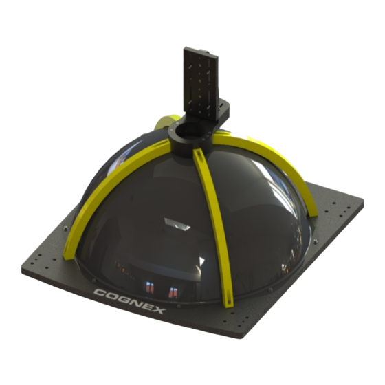
Layouts The following sections show the elements of the Trevista CI Dome and Dome Controller. Trevista CI Dome Layouts Cognex supports three sizes of the Trevista CI Dome: S, M, and L. Trevista CI Dome S System carrier Mounting holes... -
Page 27: Trevista Ci Dome M
Layouts Trevista CI Dome M System carrier Mounting holes Fitting holes Camera mount Camera adapter plate Dome aperture Dome cable... -
Page 28: Trevista Ci Dome L
Layouts Trevista CI Dome L System carrier Mounting holes Fitting holes Camera mount Camera adapter plate Dome aperture Dome cable... -
Page 29: Controller Layouts
Layouts Controller Layouts The Dome controller supports connections on the front and rear panels. Front Panel Power switch Air inlet/filter Phillips screws for replacing the air filter Device display LEDs Menu buttons Ears for securing the controller on the 19 inch rack Rear Panel Air outlets Light 0 connector... - Page 30 Layouts Digital I/O connector Name plate/serial number Fuses IEC socket for main supply line Ground connection...
-
Page 31: Installation
Installation Installation Mounting The following section provides an overview about controller, dome, and camera mounting options. Mounting the Controller The controller comes with a 19 inch housing, which you can mount on a 19 inch rack. 1. Secure the housing to the rack. 2. -
Page 32: Mounting The Camera
Installation Mounting the Camera In most cases, you can mount the camera with the camera mount and the camera adapter plate. You can secure the camera mount to the dome in four orientations. The camera mount is fastened to the dome with four screws. Two dowel pins ensure the exact adjustment of the dome and the camera mount. -
Page 33: Cabling
Installation Camera Orientation Depending on the Direction of Movement of the Inspection Object Scan Scan Multiline The orientation of the camera with reference to the dome system carrier depends on the orientation of both dome and camera. The controller must be informed about the orientation of the camera with reference to the dome system carrier when it is set up in order to ensure the correct lighting direction. - Page 34 Installation Cabling GigE/Firewire System Cabling Framegrabber System...
-
Page 35: Power Supply
The camera and framegrabber triggering is not shown here. Power Supply Before connecting to the power supply, make sure that the controller is switched off. WARNING: Use only the power supply cable provided by Cognex. Other power supply cables are not compatible. - Page 36 Installation CAUTION: Before establishing the power supply connection, make sure that the supply network meets the following requirements: 100-240 V AC +/- 10% 50-60 Hz 550 VA For more info, see Operating Environment on page 14. In order to connect to the power supply, connect the cold device plug of the power supply cable to the IEC socket (24) of the controller.
-
Page 37: Device Mode And Functional Groups
Device Mode and Functional Groups Device Mode and Functional Groups The Trevista CI Dome controller arrives with one of the following factory-set device modes that cannot be changed: Area Scan Line Scan The device mode determines the range of functions available to the controller. For example, a Trevista CI Dome setup using a controller in Area Scan mode does not support a rotary encoder. - Page 38 Device Mode and Functional Groups The camera captures four images and for each image, the object is illuminated from a different direction. Trevista CI Dome uses these input images to calculate the following output images: Slope in X direction Slope in Y direction Texture image Curvature image Image acquisition and processing in Area Scan mode:...
-
Page 39: Line Scan
Device Mode and Functional Groups Line Scan Trevista CI Dome Line Scan mode produces slope, curvature, and texture images, of a rotating or moving object. The schematic layout of the Line Scan device mode: A line-scan camera captures images where the width corresponds to the desired width of the measuring field. The object feed rate between two image acquisitions must be exactly one fourth of one line height. -
Page 40: Functional Groups
Device Mode and Functional Groups Functional Groups You can extend the default range of functions of the device modes Area Scan and Line Scan by activating optional functional groups. You must specify the desired additional functionality before placing an order for the controller. Light/Camera I/O 1 + 2 The functional group Light/Camera I/O 1 + 2 lets you use and parameterize the Light 1 + 2 and Camera I/O 1 + 2 interfaces. - Page 41 Device Mode and Functional Groups Sequence length Switch-on time of the individual channels of light 0, 1, and 2 Trigger time of cameras 0, 1, and 2 Number of sequence repeats Number of step repeats...
-
Page 42: Controller Interfaces
The ground cable must not exceed a length of 1 m (3.28 ft) and must have a wire cross section of at least 2.5 mm² (0.039 in²). Cognex recommends to use an HF band with copper braiding to enhance interference immunity. -
Page 43: Pin Assignment
Controller Interfaces Pin Assignment The following image shows the pin assignment of the Camera I/O interface: D-Sub 9-Pin Female Connector (viewed from the front) Name Description Type Level Number Out 0 TTL/OD Output 0 can be used in push/pull version with TTL level or as an TTL: 5 V open drain. -
Page 44: Connection Example
Controller Interfaces D-Sub 9-Pin Female Connector (viewed from the front) Name Description Type Level Number +24 V Camera 24 V output for the camera supply (max. 1 A). 24 V +12 V Camera 12 V output for the camera supply (max. 2 A). 12 V With hardware versions 0 and 1, pin 1 is only a TTL output. -
Page 45: Electrical Data
Controller Interfaces The following image shows output 0 or 1 used as an open-drain output. Electrical Data TTL/open-drain outputs (Out 0/1 TTL/OD) Parameter Test Condition Minimum Typical Maximum Unit Output impedance Ω Output current High-level output voltage (TTL) = 100 µA = 30 mA Low-level output voltage = 100 µA... -
Page 46: Aux I/O
Controller Interfaces Output current +24 V supply output (+24 V Camera I/O) Parameter Test Condition Minimum Typical Maximum Unit Output voltage = 0 A 23.2 24.8 = 1 A 24.6 Output current Aux I/O The Aux I/O interface is a universal interface that you can use, for example, to trigger a frame grabber. The two outputs are available as TTL, LDVS, and RS-422 variants. -
Page 47: Pin Assignment
Controller Interfaces Pin Assignment D-Sub HD 26-Pin Female Connector (viewed from the front) Name Description Type Level Number Out TTL Out 0 TTL Output 0, TTL Out TTL Out 1 TTL Output 1, TTL Out TTL Supply voltage for the TTL outputs. You can determine the level of the TTL 3.3-5 V outputs with this input. - Page 48 Controller Interfaces D-Sub HD 26-Pin Female Connector (viewed from the front) Name Description Type Level Number +3.3 V Aux 3.3 V output for supplying the TTL outputs. 3.3 V +5 V Aux IO 5 V output for supplying the TTL outputs. In 0 TTL Input 0, TTL 3.3-5 V...
-
Page 49: Connection Example
Controller Interfaces D-Sub HD 26-Pin Female Connector (viewed from the front) Name Description Type Level Number Mass/reference potential for all signals. Note: All signals have a reference to the signal ground (GND). You must connect signal ground (GND) between the devices regardless of the input or output type you use (TTL, LVDS, RS-422). -
Page 50: Electrical Data
Controller Interfaces The following image shows an example of connecting the TTL inputs of the Dome controller: The following image shows an example of connecting the LVDS inputs of the Dome controller: Electrical Data TTL output (Out 0/1 TTL) Parameter Test Condition Minimum Typical... -
Page 51: Digital I/O
Controller Interfaces TTL input (In 0/1 TTL) Parameter Test Condition Minimum Typical Maximum Unit Input impedance = 3.3 V kΩ Input voltage for low level Input voltage for high level Input current = 3.3 V = 5 V LVDS output (Out 0/1 LVDS) Parameter Test Condition Minimum... -
Page 52: Basic Circuit
Controller Interfaces Note: When the output drivers are supplied with an internal voltage, the galvanic isolation of the outputs is lost. Optionally, you can apply an external sequencer enable signal to Input 0 if you cannot or do not want to enable the sequencer from software. -
Page 53: Pin Assignment
Controller Interfaces Pin Assignment D-Sub HD 44-Pin Female Connector (viewed from the front) Pin Number Name Description Type Level In 0 Input 0 24 V In 1 Input 1 24 V In 2 Input 2 24 V In 3 Input 3 24 V In 4 Input 4... -
Page 54: Connection Example
Controller Interfaces D-Sub HD 44-Pin Female Connector (viewed from the front) Pin Number Name Description Type Level reserved Do not wire this pin. reserved Do not wire this pin. reserved Do not wire this pin. reserved Do not wire this pin. reserved Do not wire this pin. - Page 55 Controller Interfaces The following image shows an example of the connecting the outputs of the Digital I/O interface with an external supply. The following image shows an example of the connecting the outputs of the Digital I/O interface the internal supply.
-
Page 56: Electrical Data
Controller Interfaces Electrical Data Output (Output 0..7) Parameter Test Condition Minimum Typical Maximum Unit Output current per output Sum of the currents across all outputs Output voltage Out VCC = 24V, I = 0.7 A 23.5 23.8 Input voltage at Out VCC Input (Input 0..7) Parameter Test Condition... -
Page 57: Encoder
The encoder inputs (A+, A-, B+, B-) are galvanically isolated. When using encoders with ground-referenced A/B signals, this galvanic isolation is lost. Note: Cognex recommends using our programmable encoders, with which you can set the number of pulses per revolution through the Dome controller. -
Page 58: Pin Assignment
Controller Interfaces Pin Assignment D-Sub 15-Pin Female Connector (viewed from the front) Name Description Type Level Number Encoder input A+ 5-24 V Encoder input A- 5-24 V Encoder input B+ 5-24 V Encoder input B- 5-24 V Mass/reference potential for the power supply outputs, encoder inputs, and RS-485. -
Page 59: Electrical Data
Controller Interfaces The following image shows an example of a ground-referenced connection to the encoder interface. Electrical Data Encoder input (A/B +/-) Parameter Test Condition Minimum Typical Maximum Unit Differential input voltage for low level A+ - A- or B+ - B- Differential input voltage for high level A+ - A- or B+ - B-... -
Page 60: Light
You can connect the lights to the Dome controller through the Light interfaces. Light 0 Make sure to only connect Cognex trevista® lights to the “Light 0” interface. The light transmits the light data to the Dome controller after you switch on the Dome controller. -
Page 61: Training Sequence
Note: Connecting lighting with a capacitive or an inductive impedance can lead to the destruction of the Dome controller or the lighting. For trevista® lights not manufactured by Cognex, you must enter the light parameters manually. These are limited to the following parameters:... -
Page 62: Current And Voltage Monitoring
Controller Interfaces Note: The Dome controller always uses the data of Cognex lights with light data can be read out digitally. The Dome controller ignores manual data even when the parameter Light data is set to Manual. Current and Voltage Monitoring Note: The Dome controller may perform a power limitation to prevent destruction from excessive power loss. -
Page 63: Pin Assignment
Controller Interfaces Pin Assignment The following table shows the pin assignment of the Light 0 connector: D-Sub 37-Pin Female Connector (viewed from front) Pin Number Name Description Type Level 18 + 19 LED0+ LED channel 0 connection + (to the anode) 38 V 36 + 37 LED0-... - Page 64 Controller Interfaces D-Sub 37-Pin Female Connector (viewed from front) Pin Number Name Description Type Level reserved Do not wire this pin. reserved Do not wire this pin. The following table shows the pin assignment of the Light 1 and Light 2 connectors: D-Sub 15-Pin Female Connector (viewed from the front) Pin Number Name...
-
Page 65: Connection Example
Controller Interfaces Note: The positive and the negative connections of an LED channel are available though several plug pins. When you connect a light, interconnect these pins within the connector to ensure the equal distribution of current between several pins. For example, Light 1: LED0+: Pin 6 + 7 + 8, LED0-: Pin 13 + 14 + 15. Connection Example The following image shows a connection example for the Light 1 connector:... -
Page 66: Operation
Operation Operation Block Diagram Power On/Off The controller is switched on and off with the power switch on the front panel. After having been switched on, the controller needs some time for self-testing, device identification, and calibration. In this initialization phase, the controller cannot be accessed via software. You can switch the controller off at any point during operation. -
Page 67: Manual Operation Of The Dome
Operation Manual Operation of the Dome Display and retrieve the operation states and status information using the control elements display, LEDs, and buttons on the front panel. It is not possible to parameterize the controller with these control elements. Parameterization must be performed with software in the Ethernet interface. - Page 68 Operation Permanently red Critical error. Error types: Incorrect training sequence of an automatic SAC light Overtemperature of the light (only with automatic SAC lights) Disconnection of the data interface (with automatic SAC lights) Overcurrent (in switched-on state) Fault current (in switched-off state) Errors in the LED driver Flashing red Uncritical error.
-
Page 69: Display
Operation Flashing red Error. Error types: Camera I/O 0 Output 0 is overtriggered. Camera I/O 1 Output 0 is overtriggered. Camera I/O 2 Output 0 is overtriggered. Aux I/O output 0 is overtriggered. Aux I/O output 1 is overtriggered. Encoder LED State Meaning No programmable encoder connected... -
Page 70: Standard Display
Operation Standard Display The standard display is active after the startup/initialization phase. You can return to this display anytime by pressing the “ESC” button (repeatedly). Content Sequencer state: “disabled” – The sequencer is disabled. “trigger ?” – The sequencer is enabled and is waiting for a trigger. ”active”... -
Page 71: Menu
Operation Module: LedDriver LedPower Light CameraIo AuxIo Encoder … 3 - 4 Notification text Menu After pressing the “Up” or “Down” button, the menu opens. If no button is pressed for 10 seconds or the “ESC” button is pressed, the menu is closed, and the display is set back to the standard display. The small arrow left of the menu entries shows the current selection. - Page 72 Operation Content Left - Notification type: I = Information W = Warning (warning notification) E = Error (error notification) ER = ErrorRelease (withdrawn error message) Center - Notification number (continuous, hexadecimal) Right - Time stamp in milliseconds; 0 = controller starting time. After 4,294,967,295 milliseconds, it is reset to 0.
- Page 73 Operation Digital I/O The menu item “Digital i/o” shows the states of the input and output signals of the Digital I/O interface. Content Left - State of the digital inputs 0 to 7 Right - Status of the digital outputs 0 to 7 Camera I/O The menu item “Camera i/o”...
- Page 74 Operation Content Left - States of the incremental encoder signals A and B Right - Direction of movement after the functional block “Preprocessing” (direction reversal, quarter increments / full increments, and divider). A left arrow means backward; a right arrow means forward.
- Page 75 Operation Light Temperature In the menu item “Light temp.”, you can find the measured values of the temperature sensors of the lights, if available. For each sensor, the following states can be displayed: Temperature (°C) “NA” – No sensor available “INV”...
- Page 76 Operation Device Mode: Surface (trevista® DOME Standard) Cylinder (trevista® DOME Scan) Multiline (trevista® DOME Scan Multiline) Device Information In the menu item “Device information”, you can find the IP address, the serial number, the device ID, the hardware version, and the supply voltage of the LED drivers. The information does not fit on one display page. You can switch between the entries with the “Up”...
-
Page 77: Network Operation Of The Dome
Operation Content Name of the light Serial number Number of channels Operating Time In the menu item “Operating time”, you can find the operating times of the controller. Content Operating hours count (this count is not lost, even if the controller is switched off) Time after the last switching-on in hours, minutes, and seconds. -
Page 78: Image-Processing Software Sac Visionpro
Operation 10.1.1.2 10.1.1.3 10.1.1.4 10.1.1.5 10.1.1.6 10.1.1.7 10.1.1.8 192.168.32.1 192.168.32.2 192.168.32.3 192.168.32.4 192.168.32.5 192.168.32.6 192.168.32.7 192.168.32.8 When more controllers are operated in a network, a different IP address must be set for each controller. Operating more than eight controllers in a network is not possible. Required Network Settings on the Host (PC) IP address: 10.1.0.1-254;... - Page 79 Operation Loading the factory settings of the controller Updating the firmware of the trevista® controller Operating the controller in connection with the SAC Device Configurator is explained in the SAC Device Configurator documentation.
-
Page 80: Care And Maintenance
Controller Layouts on page 29 for the location of the IEC socket. Note: Use only fuses of type "T 5A H 250V". Contact your Cognex sales representative for ordering information. In addition, Cognex recommends you always replace both fuses at the same time. - Page 81 Care and Maintenance 3. Replace the existing fuses with the new fuses: 4. Put the fuse drawer back into the base of the fuse holder. The two locking tabs of the drawer must engage audibly in the base.
-
Page 82: Regulations And Conformity
Regulations and Conformity Regulations and Conformity Note: For the most current CE declaration and regulatory conformity information, see the Cognex support site: cognex.com/support. The Trevista Controller has a Regulatory Model number 50240 and meets or exceeds the requirements of all applicable standards organizations for safe operation. -
Page 83: For European Community Users
表 示用于本 部件的至 少一种 均 质 材料中所 含的危害 物 质超 过GB / T26572 - 2011 的限 制 要求 。 For European Community Users Cognex complies with Directive 2012/19/EU OF THE EUROPEAN PARLIAMENT AND OF THE COUNCIL of 4 July 2012 on waste electrical and electronic equipment (WEEE).
Need help?
Do you have a question about the VisionPro Trevista CI Dome and is the answer not in the manual?
Questions and answers