
Summary of Contents for Heden NeptoLux 3K
- Page 1 Emergency escape lighting system Installation instruction NEPTO 3K Oy Hedengren Security Ab, +358 (0)207 638 000, sales +358 (0)207 638 635, security@hedengren.fi, tuotetuki@hedengren.fi, hedengrensecurity.fi, neptolux.fi...
-
Page 2: Table Of Contents
NEPTOLUX LIST OF CONTENTS 1. GENERAL ..............................4 ............................... 5 TANDARDS ......................... 5 ABLES AND CABLE SHEATHINGS ........................5 NSTALLATION ENVIRONMENT 2. HOUSING ............................... 6 ............................. 6 NSTALLATION 3. ADDRESS BUS ............................. 8 ..............................8 RINCIPLE ....................8 NSTALLATION OF EXIT AND ROUTE LIGHTS .............................. - Page 3 NEPTOLUX 5.1.3. Voltage output 24DC ........................29 5.1.4. Inputs ............................... 30 5.1.5. Installing an extra communication card ................... 30 5.1.6. Nepto 3K networking ........................30 6. TCH-B200 ADDRESS' PROGRAMMING UNIT ..................33 7. CABLE LENGTH ............................34 ..........................34 LLUMINATION POINTS 7.1.1.
-
Page 4: General
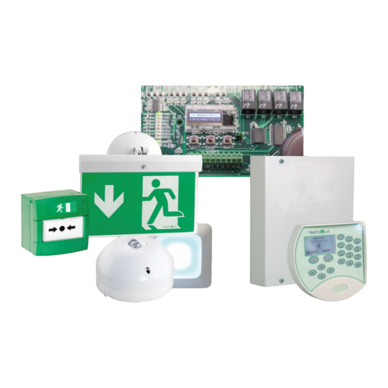
NEPTOLUX General 1. General These instructions cover the installation of the NEPTO-3K system. The features and technical values, e.g. number of lines, is dependent on the centre model. -
Page 5: Standards
NEPTOLUX General Standards The system complies with device testing, fault monitoring and reporting according to standards SFS-EN 50172 and ATS 62034 either locally or remotely. Cables and cable sheathings The cables used must be equipped with cable sheathings. All the calculations in these instructions have been done using a 0.8-mm conductor diameter. -
Page 6: Housing
NEPTOLUX Housing 2. Housing Installation The weight of the housing must be taken into account when it is fixed onto a wall. • Drill 4 pcs. 6 mm2 holes for the anchor fixings. Depth of hole must be 20-25mm. Position of holes. - Page 7 NEPTOLUX Housing V-...
-
Page 8: Address Bus
NEPTOLUX Address bus 3. Address bus Principle The system's lighting units and bus units are addressable, smart units equipped with the own batteries (lighting). The centre polls the units over approximately 0.75-s periods per address. Thus the units (127 pcs) in the entire bus are checked over < 100s. The lighting units also work as independent units if the central cable snaps. - Page 9 NEPTOLUX Address bus Installation of emergency lights to base YBN-R/3 Tighten the lighting unit to the common mounting base so that the pip on the cap is fixed in a "quarter to" position in relation to the mounting base's corresponding pip. After this, keep hold of the cap and screw clockwise until the lighting unit locks into place.
- Page 10 NEPTOLUX Address bus Fixing the signpost plastic to the signpost's frame...
- Page 11 NEPTOLUX Address bus Installing installation base seal YBX/2W Route light's flag and ceiling support installation...
-
Page 12: Lights
NEPTOLUX Address bus Lights 3.3.1. Route lights Route light NFW68-O • round light beam for capacious premises' exit lighting. • installation height 2.5 - 9 m Route light NFW68-C • rectangular light beam for corridor exit lighting. • installation height 2.5 - 9 m Technical information Light NF68... -
Page 13: Guide Light Nfw68-0
NEPTOLUX Address bus Guide light NFW68-0 • round light beam for capacious premises' exit lighting. • installation height 2.5 - 15 m Guide light NFW89-C • rectangular light beam for corridor exit lighting. • installation height 2.5 - 15 m Technical information Light NF89... - Page 14 NEPTOLUX Address bus Intensity/power consumption/illuminance Standby time Charge time 80 % Intensity LED Illuminance Average power Maximum Maximum Maximum Maximum drive [lx] consumption [W] power power power power current consumption of consumption consumption of consumption [mA] a line [mA] of a line [NU] a line [mA] of a line [NU] 0,03...
- Page 15 NEPTOLUX Address bus Intensity/power consumption/illuminance Standby time Intensity LED Illuminance Average power Maximum Maximum Maximum Maximum drive [Cd/m consumption [W] power power power power current consumption of consumption consumption of consumption [mA] a line [mA] of a line [NU] a line [mA] of a line [NU] 0,03 0,13...
-
Page 16: Emergency Exit Lighting
NEPTOLUX Address bus Emergency exit lighting Emergency exit light NFW20-x NFW20-x is an emergency exit light for 20m distance Note the type of the exit sign, the direction of the arrow depends on the type, where the x in the type marking marks the type: •... -
Page 17: Emergency Exit Light Nfw40-X
NEPTOLUX Address bus Emergency exit light NFW40-x NFW20-x is an emergency exit light for 40m distance Note the type of the exit sign, the direction of the arrow depends on the type, where the x in the type marking marks the type: •... -
Page 18: Emergency Exit Light Nah70-X
NEPTOLUX Address bus Emergency exit light NAH70-x NAH70-x is an emergency exit light for 40m distance Note the type of the exit sign, the direction of the arrow depends on the type, where the x in the type marking marks the type: •... -
Page 19: Step Lighting Unit, Na55
NEPTOLUX Address bus Base/Light alignment Step lighting unit, NA55 The light is intended for lighting stairs. Unlike other lights, the step lighting unit is installed in a normal installation box (Ensto) as a surface or embedded installation. The delivery includes equipment for both surface and embedded installation. -
Page 20: Nepto-Io
NEPTOLUX Address bus Light NA55 20 – 40 Operating voltage [VDC] (VAC) Power consumption of the line [NU] *) 10 / 0.5W Battery pack [V / mAh] 9 / 200 Dimensions (length x height x depth) [mm] 70 x 70 x 65 IP class Material ABS, fire resistant... - Page 21 NEPTOLUX Address bus Address switches: FAULT MONITORING Normal inputs, turn switch 8 in OFF position. Fault monitored inputs (only 3 and 4), turn switch 8 in ON position.
- Page 22 NEPTOLUX Address bus Unit NEPTO-IO 20 – 40 Operating voltage [VDC] (VAC) Power consumption of the line [NU] 2 / 0.1W Dimensions (housing) (width x length x height) [mm] 108 x 108 x 32...
-
Page 23: Klg Keypad Panel
NEPTOLUX NL-KLG 4. NL-KLG keypad panel General The system is operated with a keypad panel(s). A maximum of 8 keypad panels can be connected to the system. The keypad panels are connected directly to the motherboard's CPN serial communication port. You need a minimum of two conductor pairs (4-conductor) + sheath cable for connecting the keypad panel to the centre. -
Page 24: Installation
NEPTOLUX NL-KLG Installation The keypad panel is installed at 1,500 + (200) mm height. 1. Drill 4 holes for the anchor fixings. Depth of hole must be 20-25mm. Position of holes. See image. 2. Fix anchor fixings. 3. Thread the cable through the bottom plate. The housing features a recess on the top, which can be removed with a file. -
Page 25: Connection
NEPTOLUX NL-KLG Connection NEPTO 3K NEPTO-254 Panel A CPN 10 Panel B Panel – + 12V Panel + KÄYTTÖLAITTEEN OPERATING DEVICE LIITIN Cable sheath Connect the central housing to CONNECTOR Kaapeiivaippa. Liitetään keskuskotelon the cable sheath's switching point. kaapelivaipan kytkentäpisteeseen. Explanation NEPTO-3K HHL-KLG, X2... -
Page 26: Settings
NEPTOLUX NL-KLG Settings 1. The keypad panel's address is set with a rotary switch SW1. 2. Connect the 5-port plug to the ethernet switch X2 3. If necessary, adjust the display's contrast after the voltage has been switched on. 4. Connect the keypad panel to the bottom plate with a counter sunk 3 mm machine screw. Address SW 1 SW 1... -
Page 27: Start-Up
NEPTOLUX NL-KLG Start-up The display features the following text when the keypad panel is started up (voltage connected or restart): * KLG remote panel * c. 2005 Oy Hedpro Ab. If the data connection is in operation, the display will feature an address, such as Addr 1 and the program version and the text "Polling OK"... -
Page 28: Nepto-3K Connections
NEPTOLUX Nepto-3K connections 5. Nepto-3K connections SER 1 Serial communication to external devices PROG programming connector PANEL Connection for KLG keypad panels SER 2 Hedring.net INPUT IN1 – IN8 Programmable inputs OUT 1 Fault output OUT 2-4 Programmable relay outputs OUT 2-4 Programmable voltage outputs 24 VDC voltage outputs... -
Page 29: Fuses
NEPTOLUX Nepto-3K connections 5.1.1. Fuses Fuses for centre: Function Fuse Value [A] Connector 35 VAC Battery pack 12VDC Voltage for external PTC1 devices Voltage for external PTC2 OUT 5-8 devices Serial communication PTC3 PROG, SER1, SER2 outputs Keypad panel PTC4 PANEL, + 5.1.2. -
Page 30: Inputs
NEPTOLUX Nepto-3K connections 5.1.4. Inputs Input Function IN 1-8 Programmable 5.1.5. Installing an extra communication card The centre has an integrated addressable line bus, whose code is LOOP 1. Card slot LOOP 2 is for an extra card. The installation must only be done when the device is powered off. Guidelines: Detach the centre's power supply from the central card AC IN contact. - Page 31 NEPTOLUX Nepto-3K connections Technical information Information Operating voltage Power consumption (24 VDC): Dimensions (length x width x height): Network Each Nepto 3K centre uses one HEDRING.Net card. See the image for L.NET and R.NET connections' principle. The first card's R.NET is connected to the subsequent card's L.NET and so forth. The network can accommodate a maximum of 12 centres.
- Page 32 NEPTOLUX Nepto-3K connections HedRing.Net LED Colour Status Explanation Left network (L.NET) fault Left network green Right network (R.NET) fault HedRing.Net LED Colour Status Explanation Right network green Signal blue flashes network message Left serial data communication red/green flashes sporadically Right serial data communication red/green flashes sporadically red/green...
-
Page 33: Tch-B200 Address' Programming Unit
NEPTOLUX TCH-B200 address' programming unit 6. TCH-B200 address' programming unit TCH-B200 programming unit is used for programming the address for the lighting units. The device operates on a 9V battery. Button functions: • LEFT: turning the unit on, the address' unit ten. •... -
Page 34: Cable Length
NEPTOLUX Cable length 7. Cable length Illumination points The centre's line output voltage level is approximately 39V (high bit), 34V (low bit). The minimum line voltage for the lighting unit is 20V, and then the cable can be hooked with 19V (39V- 20V). -
Page 35: Examples
NEPTOLUX Cable length 7.1.2. Examples Single-storey building • A building which measures 50 x 300m. • Nepto 3K centre, use line A. • Lighting unit Branch 1: 20 pcs 40m signposts (a’ 17NU). 30 pcs 20m signposts (a’ 10NU). 25 pcs NFW68 emergency lighting units (a’ 2NU). Power consumption 690NU. -
Page 36: Multi-Storey Building
NEPTOLUX Cable length Multi-storey building • The building in question has 4 floors. • The floor space of one floor is 40 x 70m. • The distance between floors is 5m. • Nepto 3K centre, use line A and B. •... -
Page 37: Other Equipment
NEPTOLUX Cable length Other equipment The minimum operating voltage of the centre's voltage output is 10.0V. When feeding external devices from a Nepto centre power source, it is important to note the devices' operating voltage and their maximum power consumption. The devices' location in the cable is also important, i.e. - Page 38 NEPTOLUX Cable length Example 2. • 2 pcs of NL-KLG, maximum power consumption a’ 60mA, minimum operating voltage 8V. • The operating devices are located in different buildings, i.e. they are at the ends of the cable. • The maximum power running between device x, NL-KLG 1 and the centre is 60+60mA=120mA. the voltage requirement 8V 200 m HUOM!
-
Page 39: Equidistant Devices
NEPTOLUX Cable length 7.2.1. Equidistant devices The minimum operating voltage 6.5V... -
Page 40: The Minimum Operating Voltage 8.5V
NEPTOLUX Cable length The minimum operating voltage 7.5V... - Page 41 NEPTOLUX Cable length The minimum operating voltage 8.5V...
-
Page 42: Devices At Cable Ends
NEPTOLUX Cable length 7.2.2. Devices at cable ends The minimum operating voltage 6.5V... -
Page 43: The Minimum Operating Voltage 7.5V
NEPTOLUX Cable length The minimum operating voltage 7.5V Kaapelimatka verrattuna virrankulutukseen Laitteet sijoitettu kaapelin päähän. Kaapelin pituus [m] 1 johdinpari 0,5mm, 188/km 2 johdinparia 0,5mm, 94/km 3 johdinparia 0,5mm, 62,6/km 4 johdinparia 0,5mm, 47/km 8 johdinparia 0,5mm, 23,5/km... -
Page 44: The Minimum Operating Voltage 8.5V
NEPTOLUX Cable length The minimum operating voltage 8.5V... -
Page 45: Technical Information
NEPTOLUX Technical information 8. Technical information Centre Centre model NEPTO-3K 5 – 40 Operating temperature [°C] Measurements [k x l x s] [mm] 347x276x76 Weight [kg] Lighting buses [number of] 1 + 1 Lighting units per bus [pcs] Lighting points in total [pcs] Areas Network transformer 220VA / 33VAC... -
Page 46: Fault Finding
NEPTOLUX Fault finding 9. Fault finding RS485 Data connection Most commonly the serial port's communication is indicated with LEDs. Red (receiving data), Green (sending data). When the red LED is flashing, the centre is receiving data. However, that does not mean that the unit understands the data. -
Page 47: The Line's Data Communication
NEPTOLUX Fault finding 9.3.2. The line's data communication The centre is programmed to communicate with only certain address, e.g. 127 (factory setting for a lighting unit). By going through the address bases with an illuminated emergency light, you can establish whether the data communication is operating.
Need help?
Do you have a question about the NeptoLux 3K and is the answer not in the manual?
Questions and answers