Advertisement
Quick Links
Advertisement

Related Manuals for RAM RP2000

Summary of Contents for RAM RP2000
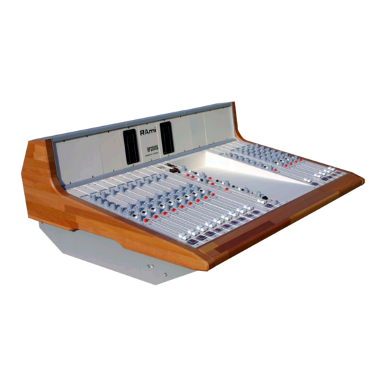
- Page 1 AUDIO VIDEO PROFESSIONNEL WWW.RAMIAUDIO.COM RP2000 Modular Broadcast Console User’s Manual...
- Page 2 RAmi RP2000S...
- Page 3 SOMMARY SUMMARY RMT 2001, Micro / Line channel ..............05 RMT 2005, Line 1 / Line 2 channel..............11 RMT 2006, Voie Line 1 / Line 2 channel ............17 RMT 2007, Digital / Analog channel ..............21 RMT 2008, Digital / Analog channel ..............27 RMT 20054, Sub channel ................
- Page 4 RAmi RP2000S...
- Page 5 MICRO / LINE CHANNEL: RMT2001 LINE / MIC MIC PRE GAIN LINE SENS TREBLE BASS AUX 1 post AUX 2 P G M 2 BALANCED MIC INSERT LINE LEFT RIGHT MIC INSERT RAmi RP2000S...
- Page 6 MICRO / LINE CHANNEL: FRONT PANEL LINE / MIC MIC PRE GAIN LINE SENS TREBLE BASS AUX 1 post AUX 2 P G M 2 RAmi RP2000S...
- Page 7 MICRO / LINE CHANNEL: FRONT PANEL Multiturn microphone gain preset ( 30 dB range). Way of use: Using key (18) (CUE) switch the channel to CUE. Switch (3) to MIC and set (5) mid range. While using the microphone, adjust pot (1) to read 0dB on peak, on the CUE vumeter. Led display for line input.
- Page 8 MICRO / LINE CHANNEL: REAR PANEL BALANCED MIC INSERT LINE LEFT RIGHT MIC INSERT XLR 3 pts Female DB15 femelle socket Earth PROGRAMMATION STOP START 1: Earth (out) (out) 2: signal + MUTE 3: signal - Jack 6.35 female PROGRAMMING PULSE HOLD STOP...
- Page 9 All inputs/outputs (XLR, 1/4 jack, Sub D) use a T filter to protect against radio frequencies and electrostatic. The RF and electrostatic flow to the RP2000 Frame. Note: All XLR pin 1 are grounded to the RP2000 frame. RAmi RP2000S...
- Page 10 MICRO / LINE CHANNEL: INTERNAL PROGRAMMING JP1/JP2 : Attenuation setting- XLR A MICRO sens -70dBu to -14dBu LINE sens (mono) -37dBu to +19dBu XLR A JP1/JP2 JP0 : Phantom power supply. * ON JP7 : START/STOP remote Line and Micro * Line only JP3/JP4 : AUX2 VOL setting AUX2 PRE FADER...
- Page 11 LINE 1 / LINE 2 CHANNEL: RMT2005 LINE 1 / LINE 2 LINE 1 LINE 2 SENS TREBLE BASS AUX 1 post AUX 2 P G M 2 LINE 2 RIGHT LEFT LINE 1 LEFT RIGHT RAmi RP2000S...
- Page 12 LINE 1 / LINE 2 CHANNEL: FRONT PANEL LINE 1 / LINE 2 LINE 1 LINE 2 SENS TREBLE BASS AUX 1 post AUX 2 P G M 2 RAmi RP2000S...
- Page 13 LINE 1 / LINE 2 CHANNEL: FRONT PANEL Led display for line input 1. Key to select Line 1 stereo balanced input or LINE 2 stereo unbalanced input. Led display for line input 2 Input sensibility pot ( 25dB range). Way of use: Using key (17) (CUE) switch the channel to CUE Switch LINE1 or LINE 2.
- Page 14 LINE 1 / LINE 2 CHANNEL: REAR PANEL LINE 2 RIGHT LEFT LINE 1 LEFT RIGHT XLR 3 pts Female DB15 femelle socket Earth PROGRAMMATION STOP START 1: Earth (out) (out) 2: signal + MUTE 3: signal - PROGRAMMING PULSE HOLD STOP 5 not connected...
- Page 15 All inputs/outputs (XLR, 1/4 jack, Sub D) use a T filter to protect against radio frequencies and electrostatic. The RF and electrostatic flow to the RP2000 Frame. Note: All XLR pin 1 are grounded to the RP2000 frame RAmi RP2000S...
- Page 16 LINE 1 / LINE 2 CHANNEL: INTERNAL PROGRAMMING JP7 : START/STOP remote Line 1 and Line 2 Line 1 only JP3/JP4 : VOL AUX2 setting VOL AUX2 JP3/JP4 AUX2 PRE FADER AUX2 POST FADER JP6 : Start chrono pulse default setting RAmi RP2000S...
- Page 17 LINE 1 / LINE 2 CHANNEL: RMT2006 LINE 1 / LINE 2 LINE 1 LINE 2 SENS AUX 1 post AUX 2 P G M 2 LINE 2 RIGHT LEFT LINE 1 LEFT RIGHT RAmi RP2000S...
- Page 18 LINE 1 / LINE 2 CHANNEL: FRONT PANEL LINE 1 / LINE 2 LINE 1 LINE 2 SENS AUX 1 post AUX 2 P G M 2 RAmi RP2000S...
- Page 19 LINE 1 / LINE 2 CHANNEL: FRONT PANEL Led display for line input 1. Key to select Line 1 stereo balanced input or LINE 2 stereo unbalanced input. Led display for line input 2 Input sensibility pot ( 25dB range). Way of use : Using key (17) (CUE) switch the channel to CUE Switch LINE1 or LINE 2.
- Page 20 LINE 1 / LINE 2 CHANNEL: REAR PANEL The RMT2006 rear panel is similar to RMT2005. See page 14 and 15. LINE 1 / LINE 2 CHANNEL: INTERNAL PROGRAMMING RMT2006 internal configuration is the same as RMT2005. See page 16. RAmi RP2000S...
- Page 21 DIGITAL / ANALOGUE CHANNEL: RMT2007 IGITAL NO LOCK LOCK ANALOG/DIGITAL ANALOG DIGITAL SENS TREBLE BASS AUX 1 post AUX 2 AES/EBU P G M 2 S/PDIF SELECT INSIDE AES/EBU OR S/PDIF DIGITAL ANALOG LEFT RIGHT RAmi RP2000S...
- Page 22 DIGITAL / ANALOGUE CHANNEL: FRONT PANEL IGITAL NO LOCK LOCK ANALOG/DIGITAL ANALOG DIGITAL SENS TREBLE BASS AUX 1 post AUX 2 P G M 2 RAmi RP2000S...
- Page 23 DIGITAL / ANALOGUE CHANNEL: FRONT PANEL Out of standard frequency or digital frame blank indicator. Standard frequency or digital frame presence indicator Key to select balanced stereo analogue audio, or digital (AES/EBU or S/PDIF) input. Input level setting (ranges 25dB ) Way of use: Using key (13) (CUE) switch the channel to CUE.
- Page 24 DIGITAL / ANALOGUE CHANNEL: REAR PANEL AES/EBU S/PDIF SELECT INSIDE AES/EBU OR S/PDIF DIGITAL ANALOG LEFT RIGHT XLR 3 pts Female DB15 femelle socket Earth PROGRAMMATION STOP START 1: Earth (out) (out) 2: signal + MUTE 3: signal - PROGRAMMING PULSE HOLD STOP...
- Page 25 All inputs/outputs (XLR, 1/4 jack, Sub D) use a T filter to protect against radio frequencies and electrostatic. The RF and electrostatic flow to the RP2000 Frame. Note: All XLR pin 1 are grounded to the RP2000 frame. RAmi RP2000S...
- Page 26 DIGITAL / ANALOGUE CHANNEL: INTERNAL PROGRAMMING JP8/JP9 Digital input configuration JP8/JP9 AES/EBU Input S/PDIF Input JP7 : START/STOP remote Digital and analogue input Analogue input only JP3/JP4 : VOL AUX2 setting JP3/JP4 AUX2 PRE FADER AUX2 POST FADER JP6 : Start chrono pulse RAmi RP2000S...
- Page 27 DIGITAL / ANALOGUE CHANNEL: RMT2008 IGITAL NO LOCK LOCK ANALOG/DIGITAL ANALOG DIGITAL SENS AUX 1 post AUX 2 AES/EBU P G M 2 S/PDIF SELECT INSIDE AES/EBU OR S/PDIF DIGITAL ANALOG LEFT RIGHT RAmi RP2000S...
- Page 28 DIGITAL / ANALOGUE CHANNEL: FRONT PANEL IGITAL NO LOCK LOCK ANALOG/DIGITAL ANALOG DIGITAL SENS AUX 1 post AUX 2 P G M 2 RAmi RP2000S...
- Page 29 DIGITAL / ANALOGUE CHANNEL: FRONT PANEL Out of standard frequency or digital frame blank indicator. Standard frequency or digital frame presence indicator Key to select balanced stereo analogue audio, or digital (AES/EBU or S/PDIF) input. Input level setting ( ranges 25dB ) Way of use: Using key (13) (CUE) switch the channel to CUE.
- Page 30 DIGITAL / ANALOGUE CHANNEL: REAR PANEL RT2008 rear panel is the same as RMT2007. See page 24 and 25. DIGITAL / ANALOGUE CHANNEL: INTERNAL PROGRAMMING RMT2006 internal configuration is the same as RMT2005. See page 26 RAmi RP2000S...
- Page 31 SUB GROUP CHANNEL: RMT2054 PREMIX IN volume treble bass volume post SUB GROUP PGM2 PREMIX IN balance SUB GROUP N-1 OUT RECORD OUTPUT INSERT IN / OUT REMOTE CONF. without SUB with SUB STUDIO RAmi RP2000S...
- Page 32 SUB GROUP CHANNEL: FRONT PANEL PREMIX IN volume treble bass volume post PGM2 balance SUB GROUP RAmi RP2000S...
- Page 33 SUB GROUP CHANNEL: FRONT PANEL Key 2 OFF indicator. KEY ON / OFF to select PREMIX input on Sub group channel. Key 2 ON indicator. Premix level. High level premix setting. Center setting does not affect tone. Medium premix level setting. Center setting does not affect tone. Bass premix level setting.
- Page 34 SUB GROUP CHANNEL: REAR PANEL SUB GROUP PREMIX IN N-1 OUT RECORD OUTPUT INSERT IN / OUT REMOTE CONF. without SUB with SUB STUDIO XLR 3 pts Male XLR 3 pts Female DB15 female socket START or ON AIR 1: Earth 1: Earth 2: Signal + 2: Signal +...
- Page 35 On Signal to Studio. All inputs/outputs (XLR, Sub D) use a T filter to protect against radio frequencies and electrostatic. The RF and electrostatic flow to the RP2000 Frame. Note: All XLR pin 1 are grounded to the RP2000 frame RAmi RP2000S...
- Page 36 SUB GROUP CHANNEL: INTERNAL PROGRAMMING JP4/JP5 : AUX2 VOL AUX2 AUX2 PRE FADER AUX2 POST FADER * default setting RAmi RP2000S...
- Page 37 HYBRID OUTPUT CHANNEL: RMT2051 R E C O R D LEVEL P G M 2 TUNER E X T P G M C U E Talkback Tel StBy H Y B R I D A Ta l k b a c k A C U E ...
- Page 38 HYBRID OUTPUT CHANNEL: FRONT PANEL R E C O R D LEVEL P G M 2 TUNER E X T P G M C U E Talkback Tel StBy H Y B R I D A Ta l k b a c k A C U E ...
- Page 39 HYBRID OUTPUT CHANNEL: FRONT PANEL RECORD SECTION: Multi turns trimers setting left/right record level. Sends “ANTENNA” signal to RECORD output. Sends “PROGRAMME 2” signal to Record output. Sends Tuner signal to “RECORD” output. Sends “PROGRAMME EXT” to “RECORD” output Cue Key selector for record signal with light indicator. ORDER SECTION: Key to send order to OUT TEL standby output.
- Page 40 HYBRID OUTPUT CHANNEL: REAR PANEL OUT RECORD OUT Tel StBY HYBRID B HYBRID A HYBRID IN / OUT XLR 3 pts Male 1 : Earth 2 : Signal + 3 : Signal - Hybrid MANAGEMENT Hybrid MANAGEMENT IN / OUT REMOTE IN / OUT REMOTE DB-15 pts Female DB-15 pts Female...
- Page 41 HYBRID OUTPUT CHANNEL: REAR PANEL Male 3 poles XLR balanced left RECORD output Male 3 poles XLR balanced right RECORD output. Male 3 poles XLR balanced output to hybrid TEL1000 /400 control. Female Sub D15 Hybrid B input / output. Balanced Input / output, at +6dBu nominal levels.
- Page 42 RAmi RP2000S...
- Page 43 OUTPUT 2 CHANNEL: ANTENNA / AUX RETURN HYBRID MANAGEMENT: RMT2052/1 A N T E N N A MONO LEVEL I N T C U E I N T B OT H E X T E X T C U E AU X R E T U R N PGM2 C U E...
- Page 44 OUTPUT 2 CHANNEL: FRONT PANEL A N T E N N A MONO LEVEL I N T C U E I N T B OT H E X T E X T C U E AU X R E T U R N PGM2 C U E RETURN...
- Page 45 OUTPUT 2 CHANNEL: FRONT PANEL ANTENNA SECTION: Broadcast key with light indicator Allows to broadcast either the signal from the console (inputs channel switched to ANTENNE) and an external signal (EXT / SATELLITE ) from (A) (B) inputs . (I.E : switching from local to national, or program supplier).EXT signal is send to ANTENNA OUT (C) and (D) via relays, allowing to broadcast EXT signal, when the console is switched off (maintenance, power supply fail...).
- Page 46 OUTPUT 2 CHANNEL: REAR PANEL HYBRID MANAGEMENT AUX 1 / AUX 2 OUTPUT IN / OUT REMOTE DB-15 pts Female connector DB-15 pts Female connector AUX2 right Hybrid RETURN OUTPUT ( Hybrid OUT to AUX2 left Console IN) Hybrid send OUTPUT (Console OUT to AUX1 right...
- Page 47 OUTPUT 2 CHANNEL: REAR PANEL Female 3 poles balanced XLR EXT PGM left input. Nominal level +6dBu. Female 3 poles balanced XLR EXT PGM right input. Nominal level +6dBu. Male 3 poles balanced XLR ANTENNE left output. Nominal level +6dBu. Male 3 poles balanced XLR ANTENNE right output.
- Page 48 RAmi RP2000S...
- Page 49 OUTPUT 2 CHANNEL: TALKBACK / PGM2-RECORD / STUDIO CONTROL ROOM / HEADPHONE CHANNEL: RMT2052/2 PUSH TA L K B AC K E X T INSERT STUDIO PRESENTER P G M 2 C U E S T U D I O P G M 2 TUNER P G M 2...
- Page 50 OUTPUT 2 CHANNEL: FRONT PANEL PUSH TA L K B AC K E X T INSERT STUDIO PRESENTER P G M 2 C U E S T U D I O P G M 2 TUNER P G M 2 TUNER E X T C U E O N...
- Page 51 OUTPUT 2 CHANNEL: FRONT PANEL ORDER SECTION: - Female XLR connector for RMT 2101 order microphone - Order level control. - Transitory key sending order to EXT output connector (M) on rear panel. - Transitory key sending order to Hybrid. - Transitory key sending order to stereo STUDIO output - Transitory key sending order to specific studio DJ-connector (N) on rear panel.
- Page 52 OUTPUT 2 CHANNEL: REAR PANEL TUNER / EXT INPUT STUDIO / DJ ORDER OUTPUT EXT ORDER OUTPUT DB-15 pts Female connector DB-15 pts Female connector Left STUDIO EXT ORDER C.ROOM red OUTPUT OUYPUT light indicator Right EXT right STUDIO OUTPUT STUDIO INPUT EXT left...
- Page 53 OUTPUT 2 CHANNEL: REAR PANEL Male 3 poles XLR stereo balanced PGM2 left output. Nominal level +6dBu Male 3 poles XLR stereo balanced PGM2 right output Nominal level +6dBu Male 3 poles XLR stereo balanced CONTROL ROOM left output Nominal level +6dBu. Male 3 poles XLR stereo balanced CONTROL ROOM right output Nominal level +6dBu.
- Page 54 RAmi RP2000S...
- Page 55 DIGITAL OUTPUT CHANNEL: RMT2068 IGITAL DIGITAL OUT SAMPLE RATE 96 kHz 48 kHz 44.1 kHz OTHER L E V E L dBFs LEFT RIGHT DIGITAL OUTPUT AES/EBU PGM 2 DIGITAL OUTPUT SELECT SAMPLE 44.1 RATE OTHER LOCK YNCHRO OUTPUT OPTION ANALOG IN PUT RAmi...
- Page 56 DIGITAL OUTPUT CHANNEL: FRONT PANEL IGITAL DIGITAL OUT SAMPLE RATE 96 kHz 48 kHz 44.1 kHz OTHER L E V E L dBFs LEFT RIGHT PGM 2 DIGITAL OUTPUT RAmi RP2000S...
- Page 57 DIGITAL OUTPUT CHANNEL: FRONT PANEL Leds, indicate the selected sampling rate. Digital Peakmeter. It allows optimum sampling setting. Multi turns sampling gain setting. Leds indicate signal sent to digital output. CUE key. Sends the AES/EBU input signal to cue circuits (vumeter and headphones). RAmi RP2000S...
- Page 58 DIGITAL OUTPUT CHANNEL: REAR PANEL DIGITAL OUTPUT AES/EBU SELECT SAMPLE 44.1 RATE OTHER LOCK YNCHRO OUTPUT OPTION ANALOG IN PUT DB15 female connector XLR 3 pts Male 1 : Earth 2 : Signal 3 : Signal RAmi RP2000S...
- Page 59 DIGITAL OUTPUT CHANNEL: REAR PANEL Male XLR 3 pins digital output AES / EBU panel connector . (Balanced 110Ω). Selects the signal sent to digital output. Sampling frequency selector. Sync output. Output frequency is the same as selected sampling frequency. Option.
- Page 60 19 INCHES 2U POWER SUPPLY: RMT2045 +15V -15V +48V ANALOG PHANTOM DIGITAL RAmi RP2000S...
-
Page 61: Power Supply: Description
POWER SUPPLY: DESCRIPTION Front panel: 1- Mains switch. 2- +5Volts light. 3- +48Volts phantom power supply light. 4- -15Volts light. 5- +15Volts light. Rear panel: Female Jaeger 8 points. CEI mains connector. Wiring: Male straight Male angled Jaeger Jaeger 8 pts Connector 8 pts Connector Wire side Wire side... - Page 62 IMPORTANT Attention RP2000 features a CEI mains connector (2 poles + earth). Earth must be necessarily connected to the electricity net. Never use this equipment without a good earth connection Check the earth quality before switching on. Should noise or hum appear when the console is connected to other equipment, never disconnect the earth, but use galvanic ...
- Page 63 DIMENSIONS: RP2000S 11 modules ....................64 14 modules ....................65 8, 16, 24, 32 modules ..................66 RAmi RP2000S...
- Page 64 RP2000S: 11 MODULES - RMT2056 ANTENNA TUNER LEFT ANTENNA LEFT -15 -12 -8 -6 -3 -4 -3 -2 -1 +2 +4 +6 RIGHT RIGHT 430 mm 485 mm RECORD PUSH RP2000S LEVEL LINE 1 / LINE 2 LINE 1 / LINE 2 LINE / MIC LINE / MIC LINE 1 / LINE 2...
- Page 65 RP2000S: 14 MODULES - RMT2057 ANTENNA TUNER LEFT ANTENNA LEFT -15 -12 -8 -6 -3 -4 -3 -2 -1 +2 +4 +6 RIGHT RIGHT 545 mm 599 mm RECORD PUSH RP2000S LEVEL LINE 1 / LINE 2 LINE 1 / LINE 2 LINE / MIC LINE / MIC LINE 1 / LINE 2...
- Page 66 RP 2000S: 8 / 16 / 24 AND 32 MODULES 8 Modules RMT2025 16 Modules RMT2029 24 Modules RMT2024 32 Modules RMT2022 WORKTOP Fitting size 27 mm 39 mm 24 modules 8 modules 16 modules 44 mm 39 mm 32 modules 1248...
-
Page 67: Options & Accessories
OPTIONS - ACCESSORIES Vumeters ......................68 RMT2061 RMT2060 Amplifier monitoring / RMT2055 ..............69 Others ......................70 RAmi RP2000S... - Page 68 VUMETERS Needle vumeter or led bargraph vumeter can be set on : ANTENNE PG 2 MONITOR Displayed levels are relatives. 0 dB reference level can be set using internal dip switches to 0dBu or +6dBu Vu meter are factory set to + 6dBu: input levels à + 6dBu are displayed 0dBu (Ask us for +12dBu levels) Vu meters are available for 8, 16, 24 and 32 modules frames.
- Page 69 AMPLIFIER MONITORING - RMT2055 RMT2055 is available for desktop RP2000 console (8, 16, 24 et 32 modules). It allows monitoring of ANTENNA, PGM2, MONITOR, et CUE by front panel selection. Led display of C.ROOM status Monitoring auto mute when using microphones in the main.
- Page 70 Input channel remote control for speak table. RMT2045 : Save power supply. RMT2069 : Switch box for spare power supply. RMT2074 : TEL400 remote control for RP2000 dash board Horloge PRT505 : Headphone amplifier Input modules remote control RAmi RP2000S...
- Page 71 7 Rue Raoul Follereau 77600 BUSSY SAINT GEORGES - FRANCE Tél. : 33 (0)1 64 66 20 20- Fax : 33 (0)1 64 66 20 30 E-mail : rami@ramiaudio.com www.ramiaudio.com All specification in this document can be modifed by RAMI without prior notice Version 1160521...
Need help?
Do you have a question about the RP2000 and is the answer not in the manual?
Questions and answers