Advertisement
Quick Links
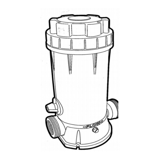
INSTALLATION GUIDE AND OPERATING INSTRUCTIONS
AUTOMATIC CHLORINE FEEDERS
8567I / 8567O / 8568I / 8568O
I) INSTALLATION
8567I / 8568I
1.Your 85671 / 85681 automatic chlorine feeder is
designed for permanent installation in the pool water
return line.
2. Always install the chlorine feeder after the heater.
If there is no heater, install after the filter. Damage to
the heater
or
filter
chlorine is allowed to flow through them.
3. 8567I / 8568I
threads. 8568I is also equipped with male threads. If
male end and union connections are desired , order
91382 PVC male union connector package. Thread or
socket adapters may also be approved for used. Only
use pipe sealants formulated and approved for use
with ABS plastic connection. Do not over tighten pipe
fitting. Proper fitting makeup is hand tight plus 1 to 1
½ turns maximum.
NOTICE: After starting up system,re-check all
connections for leaks. Re-tighten as required.
4.Refer to section II DIRECTIONS FOR USE
NOTE: Never install chlorine feeder directly into copper plumbing
as pipe damage may occur. If you have brass or bronze
backwash
valves,
or
other
consult your dealer for precautions or
your particular system.
8567O / 8568O
A. PLANNING INSTALLATION
1.The inlet connection should be made in the piping
after the pump and before the filter, mark location
on pipe.
2. The outlet connection should be made in the
piping after the heater. If no heater is being used,
connection should be made after the filter. Mark
location on pipe.
may
result if
concentrated
is furnished with 1 ½ female
sensitive
metallic compone nts,
recommendations for
3. Based on the locations from steps. No 1 and No 2,
cut tubing to required lengths be sure ends are cut
evenly and cleanly.
NOTE : Never install chlorine
plumbing as pipe damage may occur. If you have brass or
bro nze
backwash valves,
components,
consult
your
recommendations for your particular system.
B.CONNECTION TO CHLORINATOR
1. Wrap Teflon tape on large male thread of check valve and
thread it securely into outlet port of chlorinator.
NOTICE: the check valve is marked with a "dot" it also has
a ball that clicks when you shake it.
2.
Wrap teflon tape on large male thread of the inlet fitting
adapter and thread it securely into the inlet port of
chlorinator.
3.
To connect inlet tubing to chlorinator, place compression
nut over inlet tubing and nut up about 2". Insert the tubing all
the way into the inlet fitting adapter socket and, holding
tubing in place tighten nut firmly by hand. Do not over
tighten
4.
Connect outlet tubing to the check valve in the same
manner as in step 3 above.
C. CONNECTION TO PLUMBING LINES
NOTICE: The saddle fittings and clamps are designed to fit
the O.D of 1 ½" or 2" pipe.
5. Drill a 3/8" hole at location identified in step 1 of planning
installation section. Clean all burrs, shavings etc. Fit saddle
feeder
directly
into copper
or
other
sensitive
metallic
dea ler for
precautions
or
Advertisement

Subscribe to Our Youtube Channel
Summary of Contents for FibroPool 8567I
- Page 1 INSTALLATION GUIDE AND OPERATING INSTRUCTIONS AUTOMATIC CHLORINE FEEDERS 8567I / 8567O / 8568I / 8568O I) INSTALLATION 8567I / 8568I 3. Based on the locations from steps. No 1 and No 2, 1.Your 85671 / 85681 automatic chlorine feeder is...
- Page 2 A) TO CHANGE O-RING chlorine residual daily and adjust the dial valve for more or less 8567I / 8567O chlorine. The chlorine demand for pools and spas varies based 1. Read and follow instructions in Step 1 to 5 in Refilling on usage, temperature, sunlight, etc.
- Page 3 8567 I SERIES PART DESCRIPTION NUMBER REQ'D 647016703080 Cover 65431033080 O-Ring 88601004 Drain Plug W/Gasket 647016875000 Control Valve Assembly 8567O SERIES PART DESCRIPTION NUMBER REQ'D 647016703080 Cover 65431033080 O-Ring 88601004 Drain Plug W/Gasket 647016875000 Control Valve Assembly 647016807080 Inlet Fitting Adapter 647016806001 Compression Nuts 65749011080...
Need help?
Do you have a question about the 8567I and is the answer not in the manual?
Questions and answers