
Summary of Contents for SMARTFOX Pro 2
- Page 1 SMARTFOX Operating instructions Manual Version 12 - 04.2022 SMARTFOX Version - EM2 00.01.03.17 | V.3.17 www.smartfox.at w w w . s m a r t f o x . a t...
- Page 2 DECLARATION SAFETY INSTRUCTIONS WARNING Non-compliance can lead to damage to property and personal injury. The instructions given must therefore always be observed or implemented! ATTENTION Non-compliance can lead to malfunctions or damage to the unit. The instructions given must therefore always be followed or implemented! NOTE Useful tips to support you during commissioning.
-
Page 3: Table Of Contents
Regulations........................6 Dimensions........................6 Assembly ........................6 Electrical connection....................6 Hedging...........................6 Installation of SMARTFOX current transformers............7 SMARTFOX Additional current transformer..............8 Wiring diagram ........................9 Power controller & heating element 1-phase............9 Power controller & heating element 3-phase............10 Consumer via relay.....................11 Navigation through the menu .....................12 Instructions for firmware update..................13... -
Page 4: General Information
EMC Directive 2004/108/EC, and the Low Voltage Directive 2006/95/EC. Application The "SMARTFOX Pro 2" energy consumption controller is used to optimise self- consumption to a maximum in electrotechnical systems with self-power generation. All relevant data for the application are measured, displayed and used for the control. -
Page 5: Scope Of Delivery And Technical Data
SCOPE OF DELIVERY & TECHNICAL DATA Scope of delivery 1x SMARTFOX Pro 2 energy consumption controller 1x Micro SD Card 1X Current transformer 3-phase up to 80A | 100A Technical data SMARTFOX Pro Rated current 80A | 100A or via additional transformer... - Page 6 SCOPE OF DELIVERY & TECHNICAL DATA w w w . s m a r t f o x . a t...
-
Page 7: Regulations
REGULATIONS DIN EN61326 Mechanical strength DIN EN 61010 Part 1 Electrical safety DIN EN 61010 Part Housing with protective insulation, protection class II, for working voltages up to 600V (mains to neutral) pollution degree 2, measurement category CAT III DIN EN 60688 Accuracy, overload air Disconnection DIN EN 61010 Part 1, 3, 3KV 50Hz 4s... - Page 8 REGULATIONS When connecting, ensure that a suitable back-up fuse is used (line protection). The unit itself is internally fused. w w w . s m a r t f o x . a t...
- Page 9 P H O T O V O L T A I K Attention! The SMARTFOX current transformers must always be connected as shown in the picture above. (Arrows point in the direction of the consumer). w w w . s m a r t f o x . a t...
-
Page 10: Smartfox Additional Current Transformer
The SMARTFOX current transformer cable must not be cut (loss of warranty). NOTE! The SMARTFOX current transformer set can be extended up to 15m. A suitable current transformer extension must be used for this. w w w . s m a r t f o x . a t... - Page 11 CONNECTION DIAGRAM POWER CONTROLLER & HEATING ROD 1- PHASE LS+N 0003127 L2 CJG 441D 40A/I∆n0,03A G PV PLANT INVERTER CJG 441D 40A/I∆n0,03A G CONSUMER IN 3/B6 1/B16 1/B16 THE BUILDING 0V UO IO 2 4 V S0+ S0- PT1000 24V 0V RX T X 1/L1 2/T1 4/A2- 3/A1+ POWER CONTROLLER...
- Page 12 CONNECTION DIAGRAM POWER CONTROLLER & HEATING ROD 3- PHASE LS+N CJG 441D 40A/I∆n0,03A G 0003127 PV PLANT INVERTER CJG 441D 40A/I∆n0,03A G CONSUMER IN 3/B6 3/B16 1/B16 THE BUILDING 0V UO IO 24V 0V + - S0+ S0- PT1000 24V 0V RX T X -A2/B2 POWER CONTROLLER 3 PHASIG...
- Page 13 ssible!
-
Page 14: Consumer Via Relay
CONNECTION DIAGRAM CONSUMER VIA RELAY CJG 441D 40A/I∆n0,03A G 24V 0V RX TX CONSUMER IN 3/B6 BUILDING... -
Page 15: Navigation Through The Menu
NAVIGATING THROUGH THE MENU Use the arrow keys left or right to scroll through the menu. To change a value/setting, press the Enter key (cursor starts flashing). Use the arrow keys up or down to change the set value. To navigate to the first line, press the left arrow key repeatedly until the cursor jumps to the first line (cursor must flash). -
Page 16: Instructions For Firmware Update
INSTRUCTIONS FOR FIRMWARE UPDATE 1. Download firmware from www.smartfox.at/downloads. Version EM2 00.00.01.37 2. Remove the SD card. 3. Unzip the downloaded file and copy the .bin file into the main directory of the SD card. 4. Insert the SD card into the unit. -
Page 17: Displaying The Measured Values
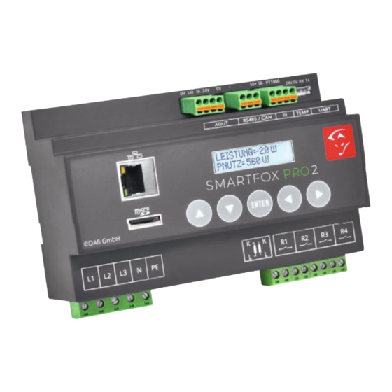
DISPLAY OF THE MEASURED VALUES NOTE! After connecting the power supply, the unit starts and automatically switches to the menu DISPLAY MEASUREMENTS. Performance and PNutz L e a s t = 2 0 w p n u Power & Benefit t z = 0 w POWER = 20W The current power is displayed. - Page 18 A N A L O G A N E R G I E = 0 . 0 0 K W H Analogue output energy = the total energy used by SMARTFOX/analogue output. Voltage S P A N N E : A = 2 3 4 V B = 2 3 5 V , C = 2 3 4 V Voltage A=234V B=235V, C=236V.
- Page 19 DISPLAY OF THE MEASURED VALUES w w w . s m a r t f o x . a t...
- Page 20 0: The relay is switched off. 1: The set switch-on condition is fulfilled, the relay has been switched on by the SMARTFOX M: The relay can be switched on regardless of the surplus situation. ATTENTION! Energy can be drawn from the mains.
- Page 21 1. Switched off - the charging station does not release a charge 2. Excess charge - automatic control by SMARTFOX 3. Forced charging - manual charging, the desired CC value must be set. ATTENTION! Energy can be drawn from the mains.
-
Page 22: Main Menu
WIFI Access Point If you set AP to ON, the SMARTFOX activates its access point. A WLAN with the name Smartfox_AP is now available. You can now connect to the SMARTFOX WIFI with your smartphone, laptop or tablet. To do this, open your network settings on the laptop, for example, and select the WLAN Smart- w w w . - Page 23 192.168.250.181. You can now access the SMARTFOX via the web interface, make settings or switch outputs. Connection WLAN via access point If you are connected to the access point of the SMARTFOX, the unit can be paired with an Internet-capable WLAN in the "NETWORK" menu. 1. Select the menu item "NETWORK 2.
- Page 24 Internet. 6. Connect your laptop, smartphone... to the same network that was selected on the SMARTFOX. The SMARTFOX can now be reached locally via the obtained IP address or http://dafi-smartfox. If the WLAN is Internet-enabled, the SMARTFOX can now be connected to the web portal my.smartfox.at.
- Page 25 The descriptions of the submenus can be found in the "Settings" section. NOTE! All settings can also be made internally via local network access or the my.smartfox.at web portal. w w w . s m a r t f o x . a t...
-
Page 26: Settings General
SETTINGS - GENERAL Current transformer S T R O M W A N D L E R E X T E R N 0 4 0 : 1 When connecting with the supplied standard 80A or 100A converters (RJ12 plug), 1:1 is set here. - Page 27 P r e s e r v e r a u t o m a t i c h Activated: The time is automatically synchronised by the NTP server. Deactivated: The time is not synchronised. The system time of the Smartfox must be set manually Time zone...
- Page 28 SETTINGS - NETWORK Network N E T Z W E R K : L A N Select the desired LAN / WLAN interface with which the SMARTFOX is to connect to the Internet. DHCP d h c p : a n DHCP ON: The network settings (IP, netmask, gateway) are queried eried automatically by the router.
- Page 29 E R V E R I P 0 9 3 . 1 8 9 . 0 2 5 . 1 8 2 The IP address of the my.smartfox.at server is 93.189.25.182. Port TCP80 & TCP5000 are required to connect to the server.
-
Page 30: Settings Analogue Output
SETTINGS - ANALOGUE OUTPUT U/IOUT U O U T : 0 - 1 0 V I O U T : 0 - 2 0 M Voltage output - UOUT Setting of the voltage output. It can be selected between 0-10V & 1-10V. The voltage output is pre-parameterised to 0-10V by default. - Page 31 SETTINGS - ANALOGUE OUTPUT L E A D I N G S T A T E S 1 - P H A S I Select whether a 1-phase or 3-phase power controller is controlled. The setting increases the accuracy of the analogue curve, but has no influence on the control behaviour of the power controller.
- Page 32 SETTINGS - ANALOGUE OUTPUT M O D U S A U T O M A T I C MODE indicates whether the time already run in automatic mode should be deducted or not (A=Automatic time is deducted, M=Manual time is not deducted). r e s t l a n d c o n t r i b u t i o n 0 0 0 m i n...
- Page 33 SETTINGS - RELAY 1 - 4 Possible control behaviour - Relay 1 - 4 r 1 W A E R M E P U M P E Z W = E I N P N = E I N Standard control behaviour (parameterisable to all relays) Consumer| Heat pump | Load shedding Special control behaviour Analogue relay (R1) | heating rod 2 (R2 &...
- Page 34 SETTINGS - RELAY 1 - 4 Heat pump Under the control behaviour heat pump, the relay is activated as soon as the set power P for the selected switch-on delay TD was surplus. If there is still enough surplus after the hold time TH has elapsed, the system does not switch off but starts the next cycle.
- Page 35 SETTINGS - RELAY 1 - 4 Relay 1 - 4 R 1 N = 0 0 0 T D = 0 0 M P = 0 0 0 0 W T H = 0 0 0 M Switch-on cycles per day - N "Switch-on cycles per day"...
- Page 36 SETTINGS - RELAY 1 - 4 Forced release relay Relay 1 - 4 R 1 F N S T = 0 0 : 0 0 D U R = 0 0 0 M M O D E = A R1 designates relay 1. Start time - ST Enter the switch-on time for the daily forced release.
-
Page 37: Settings Relay Special Functions
= 0 6 0 0 W T H = 0 0 0 M Set the nominal power of the second heating rod under P. Complete instructions Analogue relay function at www.smartfox.at/downloads w w w . s m a r t f o x . a t... - Page 38 SETTINGS - RELAY SPECIAL FUNCTIONS R2 or R3 - 2nd heating element - Temperature changeover via PT1000 The "2nd heating element" function is only active if a temperature sensor is connected to the PT1000 input. The relay switches on when the set changeover temperature of the sensor is reached and switches off again when the temperature falls below this by 2°C.
- Page 39 SETTINGS - RELAY SPECIAL FUNCTIONS Select control behaviour of heating rod2. w w w . s m a r t f o x . a t...
- Page 40 Set the desired changeover temperature. ATTENTION! The connection of a PT1000 temperature sensor is required for the function. Complete instructions "2nd heating rod function" at www.smartfox.at/downloads w w w . s m a r t f o x . a t...
- Page 41 Select the desired application of the S0 input here. Complete instructions S0 input at www.smartfox.at/downloads Pulses per unit P u l s e s p e r U n I t 0 1 0 0 p r o k W h Enter the pulse rate of the connected S0 meter here.
- Page 42 A consumption controller can be set here instead of an analogue output. e.g. Ohmpilot RTU or TCP depending on the interface (RS485 = RTU, LAN or WLAN = TCP). Complete instructions Ohmpilot www.smartfox.at/downloads w w w . s m a r t f o x . a t...
-
Page 43: Settings Inverter, Heat Pump, Battery
The complete instructions for the various inverters (Fronius, SolarEdge, Kostal, etc.) can be found at www.smartfox.at/downloads. Enter the statically assigned IP address of the inverter here. The static IP address can be omitted if the "IP Scan" setting is activated. Using the IP scan, it can take up to 15 minutes until the IP address is displayed. -
Page 44: Settings Car Charger
SETTINGS SMARTFOX CAR CHARGER C h a r g e r : c e b a b f . 0 0 2 s r e g . 0 0 6 Select the manufacturer/factory of the charging station. NOTE! Car Charger licence (art. no. 0791732486568) required. -
Page 45: Maintenance Menu
MAINTENANCE MENU Maintenance password To enter the maintenance menu, enter 9876. Delete all energy meters a l l e n e r g i e s - c a e h l e r l o e s c h e Max U M A X U : A = 2 3 1 V B = 2 3 1 V , C = 2 3 1 V... - Page 46 MAINTENANCE MENU w w w . s m a r t f o x . a t...
-
Page 47: Local Network Access
1. Read the current IP address in the MAIN MENU, e.g. 192.168.1.52. 2. Computer, laptop, smartphone... connect to the same network 3. Enter the current IP address of the SMARTFOX in the web browser. 4. The local web page of the SMARTFOX opens. -
Page 48: Connection With My.smartfox.at
2. Click on "Add device". 3. Assign a name for the unit. 4. Enter the MAC address of the SMARTFOX. (See display main menu). 5. Click on "Save". 6. If the plug symbol is displayed in green, the unit is connected to the portal. You can now make all settings via the web portal and use all monitoring functions. - Page 49 3. My SMARTFOX is in operation but does not show any characters on the display. Carry out a firmware update. 4. I cannot find my SMARTFOX on the network.
- Page 50 DAfi GmbH Niedernfritzerstraße 120 A-5531 Eben im Pongau +43 6458 20 160 support@smartfox.at www.smartfox.at...
Need help?
Do you have a question about the Pro 2 and is the answer not in the manual?
Questions and answers