
Subscribe to Our Youtube Channel
Related Manuals for NAFFCO NVT 6-115


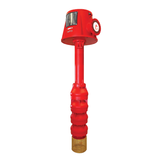
Summary of Contents for NAFFCO NVT 6-115
- Page 1 NAFFCO FIRE PUMPS VERTICAL TURBINE PUMP NVT - SERIES INSTALLATION, OPERATION & MAINTENANCE...
- Page 2 1.2. Electric Hazards Check proper earth connection of the electric, diesel, jockey controllers and electric motors. Make sure safety labels and operation labels are stuck in the controllers if damaged please get from NAFFCO and replace. Use only qualified personnel for installation and maintenance.
- Page 3 INSTALLATION OPERATION AND MAINTENANCE INSTRUCTIONS NAFFCO centrifugal pumps will give trouble-free and satisfactory service for a long time if they are properly installed and maintained periodically. Follow the instructions in this manual carefully. Do not run the pumps under operating instructions which differ from those specified by us.
-
Page 4: Installation
Fire water pump sets and control systems should be installed in accordance with this IOM maual. Failure to install the supplied NAFFCO fire pump set fully in accordance with this IOM manual will void the equipment warranty. Proper ventilation and drainage system shall be provided for fire pump room. - Page 5 VERTICAL TURBINE PUMP - NVT SERIES INSTALLATION OPERATION AND MAINTENANCE INSTRUCTIONS provide permanent and rigid support to the entire pump. Foundation area should have adequate space for future inspection and maintenance activities and should be sufficient enough to provide a solid footing. The foundation must be capable of absorbing any vibration, normal strain or shock.
- Page 6 VERTICAL TURBINE PUMP - NVT SERIES INSTALLATION OPERATION AND MAINTENANCE INSTRUCTIONS mounting flange align with the foundation bolts. Continue to lower the pump assembly until the bolts enter the holes in the base. Place wedges under the discharge head base mounting flange adjacent to the bolt holes, one under the each of the four sides.
- Page 7 VERTICAL TURBINE PUMP - NVT SERIES INSTALLATION OPERATION AND MAINTENANCE INSTRUCTIONS foundation all around. Remove the air bubbles from grout as it is poured by puddling, using a vibrator, or pumping the gout into place. Level off the grout flush with the top of the dam. Allow the grout to cure at least 48 hours and after that tighten the foundation bolts.
- Page 8 VERTICAL TURBINE PUMP - NVT SERIES INSTALLATION OPERATION AND MAINTENANCE INSTRUCTIONS ratchet pin or balls (with rotating half of the ratchet) check the motor rotation. Motor must rotate counter-clockwise when viewed from the top end. Refer Fig. No. 07-a and 07-b for the details of general arrangement of the driving mechanism for hollow shaft driver.
- Page 9 6-22 & NVT 4-60 and 1/36 to 1/54 turns per unit length (m) of pump shaft, should be made for pump models NVT 6-115, NVT 8-170, NVT 8-230, NVT 10-285 & NVT 10- 340 further after the starting position of adjustement. Further adjustements may be necessary after starting the pump if a high power consumption by the pump is observed with caused diagnosed as too small impeller clearance.
-
Page 10: Companion Flange
VERTICAL TURBINE PUMP - NVT SERIES INSTALLATION OPERATION AND MAINTENANCE INSTRUCTIONS The horizontal drivers are mounted on the base frame while shipping from the factory. Use the lifting arrangement shown in the Fig. No. 01-a for hoisting the driver assembly. Lift the driver assembly and orient it so that the holes in the base frame align with the foundation bolts. - Page 11 VERTICAL TURBINE PUMP - NVT SERIES INSTALLATION OPERATION AND MAINTENANCE INSTRUCTIONS Once the companion flanges / fly wheel disc is fixed in place, lift the drive shaft, compress it and lower it into position between mating flanges (see Fig. No. 11). drive shaft Fig.
- Page 12 VERTICAL TURBINE PUMP - NVT SERIES INSTALLATION OPERATION AND MAINTENANCE INSTRUCTIONS The cause of misalignment should be corrected before proceeding further with the installation. dial indicator top shaft drive plate Fig. No. 12 5.7. Drive Shaft Alignment Make sure that the engine crank shaft / motor shaft center line is on the same center line as the right angle gear drive shaft when examined from the top view (Fig.
- Page 13 VERTICAL TURBINE PUMP - NVT SERIES INSTALLATION OPERATION AND MAINTENANCE INSTRUCTIONS centerlines: parallel side view Fig. No. 14 shown in the Fig. No. 14 in order for the angle θ and θ be equal when the angle is measured using the method described herein.
-
Page 14: Water Tank
VERTICAL TURBINE PUMP - NVT SERIES INSTALLATION OPERATION AND MAINTENANCE INSTRUCTIONS θ θ Fig. No. 16 Bearing surfaces Bearing surfaces must be clean must be clean Adjusting knob Magnetic end of tool centered on bearing cap Magnetic end of tool centered on bearing cap Inclinometer Inclinometer... - Page 15 VERTICAL TURBINE PUMP - NVT SERIES INSTALLATION OPERATION AND MAINTENANCE INSTRUCTIONS The distance between the bottom of the strainer and the bottom of the tank should be at least one-half of the pump bowl diameter but not less than 12 in (305 mm). The distance between pump center line and tank wall should be more than the diameter of bowl.
- Page 16 VERTICAL TURBINE PUMP - NVT SERIES INSTALLATION OPERATION AND MAINTENANCE INSTRUCTIONS Install piping as straight as possible, avoiding unnecessary bends. Where necessary use 45° or long sweep 90° bends to decrease friction losses. Make sure that all piping joints are airtight. Where increasers are used in discharge line it should be concentric type. Failure to comply with this may adversely affect the performance of the pump by causing the formation of air pockets in the pipe work.
- Page 17 VERTICAL TURBINE PUMP - NVT SERIES INSTALLATION OPERATION AND MAINTENANCE INSTRUCTIONS 5.10. Check List for Fire Pump Set after installation SL. NO DESCRIPTION RESULT Sufficient distance between pump strainer bottom and tank bottom is £ £ maintained. Sufficient distance between pumps. £...
-
Page 18: Operation
VERTICAL TURBINE PUMP - NVT SERIES INSTALLATION OPERATION AND MAINTENANCE INSTRUCTIONS SL. NO DESCRIPTION RESULT Discharge pipes are provided with proper support to avoid strain on £ £ pump. Right angle gear drive is properly aligned with the pump top shaft £... - Page 19 VERTICAL TURBINE PUMP - NVT SERIES INSTALLATION OPERATION AND MAINTENANCE INSTRUCTIONS SL. NO DESCRIPTION RESULT Check the circuit wiring connections, terminals and proper earthing of £ £ equipment prior to final energization. Check the diesel level to complete the testing. Batteries are full energized £...
-
Page 20: Maintenance
VERTICAL TURBINE PUMP - NVT SERIES INSTALLATION OPERATION AND MAINTENANCE INSTRUCTIONS 6.2. Start up Start the pump against a closed discharge valve only. Once the pump has reached full speed slowly open the valve and set to the duty point. Start up of the engine and controllers shall be as given in their respective IOM manuals. Automatic starting of the pumps shall be based on pressure setting. - Page 21 VERTICAL TURBINE PUMP - NVT SERIES INSTALLATION OPERATION AND MAINTENANCE INSTRUCTIONS Make sure fuel tank is ¾ full. » » Check the diesel and jockey pump controllers and verify the selector switch is in the automatic position. Check batteries to ensure that the voltage readings on them are normal. »...
-
Page 22: Dismantling And Reassembly
VERTICAL TURBINE PUMP - NVT SERIES INSTALLATION OPERATION AND MAINTENANCE INSTRUCTIONS » Observe how long it takes the engine to crank and once started how long it takes to reach the running speed. Record the pump discharge pressures. » Check the pump packing glands to ensure proper tightness and adequate lubrication (should be slow drips – »... - Page 23 VERTICAL TURBINE PUMP - NVT SERIES INSTALLATION OPERATION AND MAINTENANCE INSTRUCTIONS Cut the coil on the marked point to form a gland packing ring. It should be cut diagonally at an angle of 45 degree. 10. Check the first ring to ensure a correct fit in the stuffing box before cutting further. 11.
- Page 24 VERTICAL TURBINE PUMP - NVT SERIES INSTALLATION OPERATION AND MAINTENANCE INSTRUCTIONS Disconnect discharge head from the discharge piping. » Clear a large area adjacent to the pump as a storage space for laying the pump horizontally for further » disassembly Place parallel timbers on the ground in the cleared area to support the pump horizontally.
- Page 25 VERTICAL TURBINE PUMP - NVT SERIES INSTALLATION OPERATION AND MAINTENANCE INSTRUCTIONS Incases where set screws are used unscrew them first. » Whereever tack weld is used grind off it carefully. » Carefully cut two “V” shaped grooves approximately 180° apart on the bowl wear ring using a diamond »...
- Page 26 VERTICAL TURBINE PUMP - NVT SERIES INSTALLATION OPERATION AND MAINTENANCE INSTRUCTIONS 8.5. Exploded View of Split case Fire Pump Fig. No. 22 Subject to change without prior notice 26 of 10 Ref. No. NVT-IOM/2020/V.01...
-
Page 27: Spare Parts Policy
NVT-****13018 Middle Line Column Pipe **** - Replace with digits that appears before and after letters “VT” in the pump model name; e.g. for NVT 6-115 replace “****” with 6115. Note – if any abnormal operation or condition is noted during the weekly test, the pump should be shut down and left in the shut down position until repairs are made. -
Page 28: Recommended Spare Parts
VERTICAL TURBINE PUMP - NVT SERIES INSTALLATION OPERATION AND MAINTENANCE INSTRUCTIONS 9.2. Recommended Spare Parts Packing » Shaft couplings » Bowl wear rings » » Impeller wear rings Gasket Set » Packing gland » Impeller keys » » Guide bearings 9.3. -
Page 29: Faults & Remedies
VERTICAL TURBINE PUMP - NVT SERIES INSTALLATION OPERATION AND MAINTENANCE INSTRUCTIONS 10. FAULTS & REMEDIES Fault Remedy Electrical circuit open or not Check circuit correct completed. accordingly. Low voltage supply to electric Check whether driver wiring is driver. correct and receiving full voltage. Check if driver is directly across the Speed is too low. - Page 30 VERTICAL TURBINE PUMP - NVT SERIES INSTALLATION OPERATION AND MAINTENANCE INSTRUCTIONS Fault Remedy Check dynamic water level in the Break suction. well. Lower bowl assembly by adding column. Consult factory for adding stages Static lift too high. ? ? ? or increase impeller diameter.
- Page 31 VERTICAL TURBINE PUMP - NVT SERIES INSTALLATION OPERATION AND MAINTENANCE INSTRUCTIONS Fault Remedy Pumping higher viscosity or Test liquid for viscosity and specific specific gravity liquid than gravity and re-evaluate the system. designed for. Misalignment. Realign pump and driver. Motor or gear drive hollow Adjust the end play as given in the shaft end play maladjustment.
- Page 32 VERTICAL TURBINE PUMP - NVT SERIES INSTALLATION OPERATION AND MAINTENANCE INSTRUCTIONS 11. FIRE PUMP INSPECTION, TESTING AND MAINTENANCE SCHEDULE Visual Description Check Change Clean Test Frequency Date Inspection A. Pump system 1. Check packing leak and lubricate Monthly 2. Check operating vibration Semiannually Annually (change...
- Page 33 VERTICAL TURBINE PUMP - NVT SERIES INSTALLATION OPERATION AND MAINTENANCE INSTRUCTIONS 11. FIRE PUMP INSPECTION, TESTING AND MAINTENANCE SCHEDULE Visual Description Check Change Clean Test Frequency Date Inspection (a) Tank level Weekly (b) Tank float switch X Weekly (c) Solenoids valve operation X Weekly (d) Strainer, filter, or dirt leg, or Quarterly...
- Page 34 VERTICAL TURBINE PUMP - NVT SERIES INSTALLATION OPERATION AND MAINTENANCE INSTRUCTIONS 11. FIRE PUMP INSPECTION, TESTING AND MAINTENANCE SCHEDULE Visual Description Check Change Clean Test Frequency Date Inspection (a) Oil level Weekly 50 hours or (b) Oil change annually 50 hours or (c) Oil filter(s) annually (d) Lube oil heater...
- Page 35 VERTICAL TURBINE PUMP - NVT SERIES INSTALLATION OPERATION AND MAINTENANCE INSTRUCTIONS 11. FIRE PUMP INSPECTION, TESTING AND MAINTENANCE SCHEDULE Visual Description Check Change Clean Test Frequency Date Inspection (g) Condition of flexible hoses and Weekly connections (h) Jacket water heater Weekly (i) Inspect duct work, clean louvers Annually...
- Page 36 VERTICAL TURBINE PUMP - NVT SERIES INSTALLATION OPERATION AND MAINTENANCE INSTRUCTIONS 11. FIRE PUMP INSPECTION, TESTING AND MAINTENANCE SCHEDULE Visual Description Check Change Clean Test Frequency Date Inspection (c) Case exterior clean and dry Monthly (d) Specific gravity or state of X Monthly charge (e) Charger and charge rate...
- Page 37 This warranty is in lieu of all other warranties, expressed or implied, including any implied warranty of merchantability or fitness for a particular purpose and the obligation and liability of NAFFCO under this warranty shall not include any transportation, any other charges, liability for direct, indirect or consequential damages and delay resulting from the defect or any other obligations or liability on the part of NAFFCO, and NAFFCO neither assumes nor authorizes any other person to assume for it any other liability in connection with such equipment.
- Page 38 VERTICAL TURBINE PUMP - NVT SERIES INSTALLATION OPERATION AND MAINTENANCE INSTRUCTIONS NOTES Subject to change without prior notice 38 of 10 Ref. No. NVT-IOM/2020/V.01...
- Page 39 Project Name :............................Location :............................Commissioned By :............................Date of Commissioning :............................Signature of Commissioning Engineer :............................
Need help?
Do you have a question about the NVT 6-115 and is the answer not in the manual?
Questions and answers