Advertisement
Quick Links
5419-716
5420-716
5542-716
Made in
Malaysia
Hecho en
Malaysia
Fabriqué en
Malaysia
V4 - Update 6/2/23
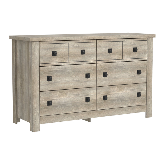
WOOD 6 DRAWER DRESSER
CÓMODA MADERA 6 CAJONES
COMMODE BOIS 6 TIROIRS
INTERACTIVE ASSEMBLY INSTRUCTIONS
Examine all packaging material for small parts that may have come loose during shipment. Periodic checks are recommended to ensure that a
components are in proper position, tight and free from damage. Keep this asembly instruction for future reference. Adult assembly is required.
Examine el material de embalaje en busca de piezas pequeñas que puedan haberse aflojado durante el transporte. Se recomienda realizar
verificaciones periódicas para asegurar que todos los componentes estén en la posición correcta, apretados y libres de daños. Guarde estas
instrucciones de ensamblaje para referencias futuras. El ensamblaje debe ser realizado por un adulto.
Examinez tous les matériaux d'emballage pour les petites pièces qui peuvent avoir été lâche pendant le transport. Des contrôles périodiques
sont recommandées afin d'assurer que tous les composants sont en bonne position, tendu et sans dommages. Gardez ces instructions de
montage pour référence future. Assemblage par un adulte est requise.
Page 1
Advertisement

Related Manuals for Hillsdale Furniture 5419-716


Summary of Contents for Hillsdale Furniture 5419-716
- Page 1 COMMODE BOIS 6 TIROIRS INTERACTIVE ASSEMBLY INSTRUCTIONS 5419-716 Examine all packaging material for small parts that may have come loose during shipment. Periodic checks are recommended to ensure that a components are in proper position, tight and free from damage. Keep this asembly instruction for future reference. Adult assembly is required.
- Page 2 Page 2...
- Page 3 Page 3...
- Page 4 Parts No Decription Parts No Description Bottom Support Bar Side Panel - L Support Bar Side Panel - R Top Panel Back Support Bar Divider Drawer Bottom Back Bottom Panel Drawer Front Top - L Back MDF Drawer Front Top - R Drawer Back Drawer Front Bottom - L Side Leg - L...
- Page 5 1. Cam Bolt EU24 2. Cam Nut 15/10 Dowel Ø8 x 50mm 50 x 52 x 4. Dowel Ø8 x 30mm Dowel Ø8 x 20mm 6. CSK Screw M4 x 38mm 69 x 24 x 8. CSK Screw M4 x 28mm 9.
- Page 6 15. PVC L Bracket Cabinet Member 12” Drawer Member 12” 18. PVC Block 35mm 19. Handle 20. Double Head Bolt M7 x 62mm 12 x 12 x Hex Key M4 Page 6...
- Page 7 1. Mounting L Bracket 2. Flat Washer M6 x 16mm 3. Screw #10 x 16mm Screw M4 x 38mm 5. Wall Plug Page 7...
- Page 8 SPECIAL TIPS FOR FITTING DRAWER CONSEJOS ESPECIALES PARA EL MONTAJE DEL CAJÓN CONSEILS SPÉCIAUX POUR LE MONTAGE DU TIROIR DRAWER RUNNER - A FRONT BACK SECOND HOLE ● Fix the first screw on the second hole on drawer runner as shown. ●...
- Page 9 Assembly / Montaje / Assemblage STEP 1 / ETAPA 1 / ÉTAPE 1 20 x (2 x) STEP 2 / ETAPA 2 / ÉTAPE 2 16 x (2 x) Page 9...
- Page 10 STEP 3 / ETAPA 3 / ÉTAPE 3 (2 x) STEP 4 / ETAPA 4 / ÉTAPE 4 12 x Page 10...
- Page 11 STEP 5 / ETAPA 5 / ÉTAPE 5 12 x STEP 6 / ETAPA 6 / ÉTAPE 6 16 x Page 11...
- Page 12 STEP 7 / ETAPA 7 / ÉTAPE 7 24 x 12 x STEP 8 / ETAPA 8 / ÉTAPE 8 18 x Page 12...
- Page 13 STEP 9 / ETAPA 9 / ÉTAPE 9 STEP 10 / ETAPA 10 / ÉTAPE 10 Page 13...
- Page 14 STEP 11 / ETAPA 11 / ÉTAPE 11 STEP 12 / ETAPA 12 / ÉTAPE 12 Page 14...
- Page 15 STEP 13 / ETAPA 13 / ÉTAPE 13 STEP 14 / ETAPA 14 / ÉTAPE 14 Page 15...
- Page 16 STEP 15 / ETAPA 15 / ÉTAPE 15 DO NOT TIGHTEN NE SERREZ PAS NO APRIETE STEP 16 / ETAPA 16 / ÉTAPE 16 Page 16...
- Page 17 STEP 17 / ETAPA 17 / ÉTAPE 17 STEP 18 / ETAPA 18 / ÉTAPE 18 Page 17...
- Page 18 STEP 19 / ETAPA 19 / ÉTAPE 19 STEP 20 / ETAPA 20 / ÉTAPE 20 Page 18...
- Page 19 STEP 21 / ETAPA 21 / ÉTAPE 21 STEP 22 / ETAPA 22 / ÉTAPE 22 TIGHTEN BOTH SERREZ LES DEUX APRIETE AMBOS Page 19...
- Page 20 STEP 23 / ETAPA 23 / ÉTAPE 23 STEP 24 / ETAPA 24 / ÉTAPE 24 Page 20...
- Page 21 STEP 25 / ETAPA 25 / ÉTAPE 25 STEP 26 / ETAPA 26 / ÉTAPE 26 Page 21...
- Page 22 STEP 27 / ETAPA 27 / ÉTAPE 27 STEP 28 / ETAPA 28 / ÉTAPE 28 Page 22...
- Page 23 STEP 29 / ETAPA 29 / ÉTAPE 29 STEP 30 / ETAPA 30 / ÉTAPE 30 Page 23...
- Page 24 STEP 31 / ETAPA 31 / ÉTAPE 31 12 x STEP 32 / ETAPA 32 / ÉTAPE 32 12 x x2 / Page 24...
- Page 25 STEP 33 / ETAPA 33 / ÉTAPE 33 12 x STEP 34 / ETAPA 34 / ÉTAPE 34 12 x Page 25...
- Page 26 STEP 35 / ETAPA 35 / ÉTAPE 35 STEP 36 / ETAPA 36 / ÉTAPE 36 Page 26...
- Page 27 STEP 37 / ETAPA 37 / ÉTAPE 37 (6 x) STEP 38 / ETAPA 38 / ÉTAPE 38 24 x (6 x) Page 27...
- Page 28 STEP 39 / ETAPA 39 / ÉTAPE 39 24 x (6 x) STEP 40 / ETAPA 40 / ÉTAPE 40 12 x x2 / Page 28...
- Page 29 IMPORTANT: THIS UNIT MUST BE SECURE TO THE WALL TO HELP PREVENT TIPOVER. FOLLOW THESE INSTRUCTIONS TO INSTALL THE ANTI-TIPPING SAFETY BRACKET PROVIDED WITH THIS PRODUCT. IMPORTANTE: ESTA UNIDAD DEBE ESTAR SEGURA A LA PARED PARA AYUDAR A PREVENIR EL TIPOVER. SIGA ESTAS INSTRUCCIONES PARA INSTALAR EL SOPORTE DE SEGURIDAD ANTI-TIPPING PROPORCIONADO CON ESTE PRODUCTO.
- Page 30 STEP 39 / ETAPA 39 / ÉTAPE 39 Drywall anchor that supplied with this product is general purpose wall plug only. Consult your local hardware store for appropriate anchors for the type of wall you intend to securely attach the safety bracket. Ancla de paneles de yeso que se suministra con este producto es enchufe de pared de propósito general solamente.
- Page 31 OPTION 1: Attachment into a wall stud (preferred method) Using a stud finder, locate a stud in the wall. Place your unit against the wall, with the safety bracket aligned in this location. To make driving the screw easier, you can drill a 3mm diameter pilot hole through the safety bracket into the stud.
- Page 32 STEP 40 / ETAPA 40 / ÉTAPE 40 Put the Drawer that has afixed anti tip warning label in the top drawer position Coloque el cajón que tiene una etiqueta de advertencia anti punta fija en la posición superior del cajón Placez le tiroir qui a une étiquette d’avertissement anti-pointe afixed dans la position du tiroir supérieur Page 32...
- Page 33 STEP 41 / ETAPA 41 / ÉTAPE 41 35 lbs 25 lbs 25 lbs This product is designed to withstand the weight vindicated on the plan. We are not responsible for the breakage of parts or any injury caused by failure to comply with this recommendation.
Need help?
Do you have a question about the 5419-716 and is the answer not in the manual?
Questions and answers