
Related Manuals for Valcom V-9989

Summary of Contents for Valcom V-9989
- Page 1 V-9989 Multi-Messager USB Installation & User Manual Valcom • 5614 Hollins Road • Roanoke, VA • 24019 Support: 1-800-VALCOM1 • HQ: 1-540-563-2000 • FAX: 1-540-362-9800 ww w.v a l c o m. c o m • is@val com .com...
-
Page 3: Table Of Contents
USB drive. Introduction: Valcom’s Multi-Messager USB is a solid-state digital message repeater that installs easily into any messaging application that requires a continuous, timed or triggered message play. Up to 99 messages in the MP3 format can be stored on industry standard USB flash drives and triggered by the eight triggered inputs or a built-in timer circuit. -
Page 4: Multi-Messager Usb Layout Summary
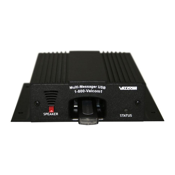
Multi-Messager USB Layout Summary Front of Unit SPEAKER - The SPEAKER switch can be turned ON and OFF to monitor audio. The switch has no effect on the audio output connections on the rear of the unit. Switch should normally be kept OFF. USB PLUG - The USB drive is inserted here to play audio. - Page 5 Bottom of unit BGM - This pot is used to control the final output level of the background music that is fed through the units BGM INPUT on the I/O CONNECTOR on the rear of the unit. Volume up is counter-clockwise, volume down is clockwise.
-
Page 6: Installation
Installation: The Multi-Messager should be installed using the following steps outlined below: Step 1: Wire the terminal blocks that are supplied with the kit. Use the chart below to wire the terminal blocks for the features that are applicable to your application. Two terminal blocks, two RCA audio cords and a screwdriver have been supplied in the accessory kit. - Page 7 Step 2: Set the DIP switches for the features that will be used. The Mutli-Messager USB has several features that are activated by setting the DIP switches on the bottom of the unit. Changes to these DIP switches must be done with the power OFF. TIMER - DIP switch positions SW1 to SW4 are used to configure the stored message timer for message slots 9 through 99.
- Page 8 CONTINUOUS TRIGGER/PLAY ONCE - DIP switch position SW6 is used select the play once or continuous trigger feature for message slots 1 through 8 ONLY. When this DIP switch is set to “ON” the unit will play message selected continuously, as long as trigger is applied.
- Page 9 Step 3: Install Multi-Messager USB hardware Step 3.1: Wall or shelf mount the unit. Screws and rubber feet are supplied in the accessory kit. Step 3.2: Verify power switch on rear of unit is in OFF position. Attach the included power pack to a wall or power strip receptacle, then attach the other end to the jack on the rear of the unit labeled 12VDC.
-
Page 10: Message Programming & Operation
Message Programming & Operation: All messages that are available for the Multi-Messager USB to play are stored on an industry standard USB flash drive. Messages must be labeled correctly so they will automatically be placed into virtual message “slots” on the unit. -
Page 11: Warranty & Fcc
This warranty is in lieu of and excludes all other warranties expressed or implied, and in noevent shall Valcom, Inc. be liable for any anticipated profits, consequential damages, loss oftime or other losses incurred by the buyer in connection with the purchase, operation or useof the product. - Page 12 5614 Hollins Road Roanoke, VA 24019 Support: 1-800-VALCOM1 HQ: 1-540-563-2000 Fax: 1-540-362-9800 www.valcom.com is@valcom.com Rev. A - 04/07...
Need help?
Do you have a question about the V-9989 and is the answer not in the manual?
Questions and answers