Table of Contents
Advertisement
Quick Links
Proxim Wireless
Gigalink 6451e
Field Installation and Service Manual
THIS DEVICE COMPLIES WITH PART 15 OF THE FCC RULES. OPERATION IS SUBJECT TO
THE FOLLOWING TWO CONDITIONS. (1) THIS DEVICE MAY NOT CAUSE HARMFUL
INTERFERENCE, AND (2) THIS DEVICE MUST ACCEPT ANY INTERFERENCE RECEIVED,
INCLUDING INTERFERENCE THAT MAY CAUSE UNDESIRED OPERATION.
IF THIS PRODUCT IS SUSPECTED OF CAUSING HARMFUL INTERFERENCE WITH OTHER
EQUIPMENT, DISCONTINUE OPERATION IMMEDIATELY AND CONTACT TERABEAM.
THE INSTALLER OF THIS RADIO EQUIPMENT MUST ENSURE THAT THE ANTENNA IS
LOCATED OR POINTED SUCH THAT IT DOES NOT EMIT RF FIELD IN EXCESS OF HEALTH
CANADA LIMITS FOR THE GENERAL POPULATION; CONSULT SAFETY CODE 6,
OBTAINABLE FROM HEALTH CANADA'S WEBSITE WWW.HC-SC.GC.CA/RPB.
FCC ID # O2700001-30-30, IC ID #: 4505A-00013031
Advertisement
Table of Contents

Related Manuals for TERABEAM Gigalink 6451e

Summary of Contents for TERABEAM Gigalink 6451e
- Page 1 INCLUDING INTERFERENCE THAT MAY CAUSE UNDESIRED OPERATION. IF THIS PRODUCT IS SUSPECTED OF CAUSING HARMFUL INTERFERENCE WITH OTHER EQUIPMENT, DISCONTINUE OPERATION IMMEDIATELY AND CONTACT TERABEAM. THE INSTALLER OF THIS RADIO EQUIPMENT MUST ENSURE THAT THE ANTENNA IS LOCATED OR POINTED SUCH THAT IT DOES NOT EMIT RF FIELD IN EXCESS OF HEALTH CANADA LIMITS FOR THE GENERAL POPULATION;...
- Page 3 Gigalink™ transceiver. Copyright © 2006 Proxim Wireless All Rights Reserved Terabeam is a registered trademark of Proxim Wireless. Gigalink™ and Gigamon™ are trademarks of Proxim Wireless. Federal Communications Commission (FCC) Compliance Statement This equipment is designed to comply with the limits for a Class A digital device, pursuant to Title 47, Volume 1, Part 15.255 of the FCC rules.
- Page 4 Safety Information The Gigalink 6451e does not pose a hazard under any reasonably foreseeable condition of normal operations. The Gigalink 6451e is an IEC Class 1 laser product in accordance with the International Electrotechnical Commission (IEC) Standard (IEC 60825-1:1993+A1:1997+A2:2001). The Gigalink 6451e also complies with the U.S.
-
Page 5: Table Of Contents
Monitoring Gigalink Terminals....................6-6 Configuring Gigalink Terminals ..................6-11 Monitoring and Routine Maintenance..............7-1 Table of Contents Proxim Wireless Gigalink 6451e Field Installation and Service Manual Document Number: 040-1234-0000 / Revision: F Release Date: 10/14/04 / Print Date: 09/27/06 Proprietary and Confidential... - Page 6 Handling and Connecting Fiber Optic Cable Transceiver MIB Revised Outdoor Power Module design Table of Contents Proxim Wireless Gigalink 6451e Field Installation and Service Manual Document Number: 040-1234-0000 / Revision: F Release Date: 10/14/04 / Print Date: 09/27/06 Proprietary and Confidential...
- Page 7 Mounting Hardware for the Universal AC Power Module ............4-5 DC Power Interface ........................4-7 Connections for the Universal AC Power Module..............4-8 Table of Contents Proxim Wireless Gigalink 6451e Field Installation and Service Manual Document Number: 040-1234-0000 / Revision: F Release Date: 10/14//04 / Print Date: 09/27/06 Proprietary and Confidential...
- Page 8 Select Gigalink Dialog Box ....................8-2 Gigamon Main Window (Run Mode)..................8-2 Table of Contents Proxim Wireless Gigalink 6451e Field Installation and Service Manual Document Number: 040-1234-0000 / Revision: F Release Date: 10/14/04 / Print Date: 09/27/06 Proprietary and Confidential...
- Page 9 SNMP simple network management protocol technical assistance center transmit Acronyms and Abbreviations Proxim Wireless Gigalink 6451e Field Installation and Service Manual Document Number: 040-1234-0000 / Revision: F Release Date: 10/14/04 / Print Date: 09/27/06 Proprietary and Confidential...
-
Page 11: Introduction
Terabeam Gigalink™ 6451e terminal, a high-performance, millimeter wave (MMW) radio communication system. The Gigalink 6451e supports Gigabit Ethernet/1000Base-SX/LX (1 Gbps). This document presents a brief overview of the Gigalink and its components and includes discussions of system requirements; installation and assembly; alignment; software setup; monitoring and routine maintenance;... -
Page 12: Installation Assumptions
Changes to this manual may be made from time to time. When this occurs, these changes will be issued as errata and posted on the Terabeam Extranet (www.terabeam.com). Customers are advised to check the Web site periodically and prior to installation for applicable errata. -
Page 13: System Overview
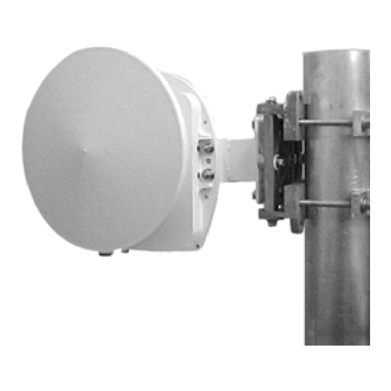
AC power module are provided in Table 2-2. Figure 2-1: Gigalink Transceiver Standard Transceiver outdoor mount Chapter 2 System Overview Proxim Wireless Gigalink 6451e Field Installation and Service Manual Document Number: 040-1234-0000 / Revision: F Release Date: 10/14/04 / Print Date: 09/27/06 Proprietary and Confidential... -
Page 14: Gigalink Components
100Base-TX adapter cable • Pole-mounted gimbal • Mount arm (and associated hardware) Chapter 2 System Overview Proxim Wireless Gigalink 6451e Field Installation and Service Manual Document Number: 040-1234-0000 / Revision: F Release Date: 10/14/04 / Print Date: 09/27/06 Proprietary and Confidential... -
Page 15: Gigalink Transceiver
Note: The transceiver is shown with the connector interface caps removed. Chapter 2 System Overview Proxim Wireless Gigalink 6451e Field Installation and Service Manual Document Number: 040-1234-0000 / Revision: F Release Date: 10/14/04 / Print Date: 09/27/06 Proprietary and Confidential... -
Page 16: Dc Power Connector Assembly
Figure 2-5: Fiber Loop-Back Jumper Cable connectors Chapter 2 System Overview Proxim Wireless Gigalink 6451e Field Installation and Service Manual Document Number: 040-1234-0000 / Revision: F Release Date: 10/14/04 / Print Date: 09/27/06 Proprietary and Confidential... -
Page 17: Adapter Cable
Figure 2-7: 100Base-TX Adapter Cable Chapter 2 System Overview Proxim Wireless Gigalink 6451e Field Installation and Service Manual Document Number: 040-1234-0000 / Revision: F Release Date: 10/14/04 / Print Date: 09/27/06 Proprietary and Confidential... -
Page 18: Mount Arm
(2) interface plate Azimuth axis eyebolt Azimuth hex bolts Chapter 2 System Overview Proxim Wireless Gigalink 6451e Field Installation and Service Manual Document Number: 040-1234-0000 / Revision: F Release Date: 10/14/04 / Print Date: 09/27/06 Proprietary and Confidential... -
Page 19: Optional Universal Ac Power Module
Optional Universal AC Power Module Refer to Appendix E, Universal AC Power Module. Chapter 2 System Overview Proxim Wireless Gigalink 6451e Field Installation and Service Manual Document Number: 040-1234-0000 / Revision: F Release Date: 10/14/04 / Print Date: 09/27/06 Proprietary and Confidential... -
Page 21: Pre-Installation Planning
30 cm (12 in.). Possible obstructions include potential snow buildup on raised structures Chapter 3 Pre-Installation Planning Proxim Wireless Gigalink 6451e Field Installation and Service Manual Document Number: 040-1234-0000 / Revision: F Release Date: 10/14/04 / Print Date: 09/27/06 Proprietary and Confidential... -
Page 22: Mounting
(40.6-cm [16-in.] cinder blocks) is used. A protective rubber mat, such as the Valmont Microflect Model B1564, must be installed to protect the roof membrane. The Gigalink 6451e cannot be mounted directly to a wall. If a free-standing pole mount is not an option, a wall-mounted pole can be used. -
Page 23: Electrical Service
Terabeam-provided DC connector (see Figure 3-2). A waterproof cord marked with W-A or W, such as a type SJOOW cord, is recommended. Detailed instructions for attaching the DC connector assembly to the power cord are provided in Appendix A. -
Page 24: Dc Power Cabling Diagram
DC Cable. A spare DC connector kit is supplied and should be wired per Table 3-2. Chapter 3 Pre-Installation Planning Proxim Wireless Gigalink 6451e Field Installation and Service Manual Document Number: 040-1234-0000 / Revision: F Release Date: 10/14/04 / Print Date: 09/27/06... -
Page 25: Network Planning
Ethernet communication with a field service laptop (see Figure 3-4). Chapter 3 Pre-Installation Planning Proxim Wireless Gigalink 6451e Field Installation and Service Manual Document Number: 040-1234-0000 / Revision: F Release Date: 10/14/04 / Print Date: 09/27/06 Proprietary and Confidential... -
Page 26: Values For Gigalink Optical Interface Parameters
-20 to -14 100Base-FX multi-mode (1310 nm) (62.5/125- µm or 50/125-µm multi-mode fiber) Chapter 3 Pre-Installation Planning Proxim Wireless Gigalink 6451e Field Installation and Service Manual Document Number: 040-1234-0000 / Revision: F Release Date: 10/14/04 / Print Date: 09/27/06 Proprietary and Confidential... -
Page 27: Tools And Equipment
Chapter 3 Pre-Installation Planning Proxim Wireless Gigalink 6451e Field Installation and Service Manual Document Number: 040-1234-0000 / Revision: F Release Date: 10/14/04 / Print Date: 09/27/06... -
Page 29: Installation
When unpacking the Gigalink terminals, installers should inspect the components to verify that everything has been received and is intact. If any item is missing, installers should contact the Terabeam TAC. The following components are included with every Gigalink 6451e terminal. •... -
Page 30: Attaching The Mount Arm To The Pole-Mounted Gimbal
3. After positioning mount assembly on pipe in direction of remote terminal, tighten both of the mount clamps to a torque of 15 ft-lbs. Chapter 4 Installation Proxim Wireless Gigalink 6451e Field Installation and Service Manual Document Number: 040-1234-0000 / Revision: F Release Date: 10/14/04 / Print Date: 09/27/06... - Page 31 +/- 45 degrees Figure 4-4: Adjusting the Elevation Elevation axis adjustment screw 3/8-in. elevation axis bolts (2) Chapter 4 Installation Proxim Wireless Gigalink 6451e Field Installation and Service Manual Document Number: 040-1234-0000 / Revision: F Release Date: 10/14/04 / Print Date: 09/27/06 Proprietary and Confidential...
-
Page 32: Transceiver Installation
Figure 4-6: Attaching the Transceiver to the Mount Arm Mount arm Transceiver Hardware Chapter 4 Installation Proxim Wireless Gigalink 6451e Field Installation and Service Manual Document Number: 040-1234-0000 / Revision: F Release Date: 10/14/04 / Print Date: 09/27/06 Proprietary and Confidential... -
Page 33: Electrical Connections
If the Gigalink is going to be run on facility-provided DC power, a DC power cord should have been built using the Terabeam-provided DC power connector assembly as part of pre-installation planning (see Section 3.3, Electrical Service). The procedure for connecting power to the Gigalink is as... - Page 34 WARNING – A potential shock hazard exists when working with -48-VDC power. All connections should be made with the power off. Chapter 4 Installation Proxim Wireless Gigalink 6451e Field Installation and Service Manual Document Number: 040-1234-0000 / Revision: F Release Date: 10/14/04 / Print Date: 09/27/06...
-
Page 35: Network Connections
3. The Gigalink configuration steps are detailed in Chapter 5, Setup and Operation. These steps are necessary for the proper operation of the Gigalink terminal. Chapter 4 Installation Proxim Wireless Gigalink 6451e Field Installation and Service Manual Document Number: 040-1234-0000 / Revision: F Release Date: 10/14/04 / Print Date: 09/27/06 Proprietary and Confidential... - Page 36 FC connectors of the supplied loop- back jumper cable to the FC data ports on the Gigalink. Chapter 4 Installation Proxim Wireless Gigalink 6451e Field Installation and Service Manual Document Number: 040-1234-0000 / Revision: F Release Date: 10/14/04 / Print Date: 09/27/06...
-
Page 37: Setup And Operation
Select an adapter and click OK. Figure 5-1: Initial Gigamon Main Window Chapter 5 Setup and Operation Proxim Wireless Gigalink 6451e Field Installation and Service Manual Document Number: 040-1234-0000 / Revision: F Release Date: 10/14/04 / Print Date: 09/27/06 Proprietary and Confidential... -
Page 38: Select Gigalink Dialog Box
Gigalink terminal (see Figure 5-3). Figure 5-2: Select Gigalink Dialog Box Chapter 5 Setup and Operation Proxim Wireless Gigalink 6451e Field Installation and Service Manual Document Number: 040-1234-0000 / Revision: F Release Date: 10/14/04 / Print Date: 09/27/06... -
Page 39: Final Alignment
This procedure will ensure the main lobe will be located. Chapter 5 Setup and Operation Proxim Wireless Gigalink 6451e Field Installation and Service Manual Document Number: 040-1234-0000 / Revision: F Release Date: 10/14/04 / Print Date: 09/27/06 Proprietary and Confidential... -
Page 40: Gigamon Main Window (Non-Graph Mode)
Chapter 5 Setup and Operation Proxim Wireless Gigalink 6451e Field Installation and Service Manual Document Number: 040-1234-0000 / Revision: F Release Date: 10/14/04 / Print Date: 09/27/06... - Page 41 Click Save to save the current Gigalink information in a text file for later review. This information can be used to evaluate ongoing transceiver performance. Chapter 5 Setup and Operation Proxim Wireless Gigalink 6451e Field Installation and Service Manual Document Number: 040-1234-0000 / Revision: F Release Date: 10/14/04 / Print Date: 09/27/06 Proprietary and Confidential...
-
Page 42: Removing Gigamon Software
SNMP/MIBS folder. Open the MIB text file and copy it into the management system. Details regarding the MIB are provided in Appendix D. Chapter 5 Setup and Operation Proxim Wireless Gigalink 6451e Field Installation and Service Manual Document Number: 040-1234-0000 / Revision: F Release Date: 10/14/04 / Print Date: 09/27/06... -
Page 43: Using The Gigamon Application
Ethernet adapter that is connected to the transceiver and click OK. Alternately, the Select Gigalink dialog box includes a Select NIC option. Chapter 6 Using Gigamon Software Proxim Wireless Gigalink 6451e Field Installation and Service Manual Document Number: 040-1234-0000 / Revision: F Release Date: 10/14/04 / Print Date: 09/27/06 Proprietary and Confidential... -
Page 44: Main Window
Figure 6-1: Main Window (Graph Mode) Figure 6-2: Main Window (Non-Graph Mode) Chapter 6 Using Gigamon Software Proxim Wireless Gigalink 6451e Field Installation and Service Manual Document Number: 040-1234-0000 / Revision: F Release Date: 10/14/04 / Print Date: 09/27/06 Proprietary and Confidential... -
Page 45: Select Gigalink Dialog Box
Log File Path. The log file path will be displayed below the buttons when the logging function is active. Chapter 6 Using Gigamon Software Proxim Wireless Gigalink 6451e Field Installation and Service Manual Document Number: 040-1234-0000 / Revision: F Release Date: 10/14/04 / Print Date: 09/27/06 Proprietary and Confidential... - Page 46 Chapter 6 Using Gigamon Software Proxim Wireless Gigalink 6451e Field Installation and Service Manual Document Number: 040-1234-0000 / Revision: F Release Date: 10/14/04 / Print Date: 09/27/06...
- Page 47 Text-Based Status Display. The text-based status display at the bottom of the screen provides the status information. Chapter 6 Using Gigamon Software Proxim Wireless Gigalink 6451e Field Installation and Service Manual Document Number: 040-1234-0000 / Revision: F Release Date: 10/14/04 / Print Date: 09/27/06 Proprietary and Confidential...
-
Page 48: Monitoring Gigalink Terminals
Note that if no Gigalink transceivers are detected, the serial number field will read 0. Chapter 6 Using Gigamon Software Proxim Wireless Gigalink 6451e Field Installation and Service Manual Document Number: 040-1234-0000 / Revision: F Release Date: 10/14/04 / Print Date: 09/27/06... - Page 49 Figure 6-4: Save Gigalink Info in a File As Dialog Box Chapter 6 Using Gigamon Software Proxim Wireless Gigalink 6451e Field Installation and Service Manual Document Number: 040-1234-0000 / Revision: F Release Date: 10/14/04 / Print Date: 09/27/06 Proprietary and Confidential...
- Page 50 Gigamon as necessary. Figure 6-5: Sample of Gigamon Save Info As Logfile Chapter 6 Using Gigamon Software Proxim Wireless Gigalink 6451e Field Installation and Service Manual Document Number: 040-1234-0000 / Revision: F Release Date: 10/14/04 / Print Date: 09/27/06...
-
Page 51: Descriptions Of Logged And Saved Data
Microsoft Excel spreadsheet. Chapter 6 Using Gigamon Software Proxim Wireless Gigalink 6451e Field Installation and Service Manual Document Number: 040-1234-0000 / Revision: F Release Date: 10/14/04 / Print Date: 09/27/06 Proprietary and Confidential... - Page 52 Stop Logging or exits Gigamon. Figure 6-8: Gigalink Menu Screen with Logging Activated Chapter 6 Using Gigamon Software 6-10 Proxim Wireless Gigalink 6451e Field Installation and Service Manual Document Number: 040-1234-0000 / Revision: F Release Date: 10/14/04 / Print Date: 09/27/06 Proprietary and Confidential...
-
Page 53: Configuring Gigalink Terminals
Gateway IP. This required parameter identifies the address of the router that will accept IP traffic to other subnets. Chapter 6 Using Gigamon Software 6-11 Proxim Wireless Gigalink 6451e Field Installation and Service Manual Document Number: 040-1234-0000 / Revision: F Release Date: 10/14/04 / Print Date: 09/27/06 Proprietary and Confidential... - Page 54 Click Apply after the values to be monitored are specified. Chapter 6 Using Gigamon Software 6-12 Proxim Wireless Gigalink 6451e Field Installation and Service Manual Document Number: 040-1234-0000 / Revision: F Release Date: 10/14/04 / Print Date: 09/27/06...
-
Page 55: Ranges For Snmp Trap Threshold Settings
Gigamon Main window. While Disabled, the network Rx display and network data in the log files will reflect N/A (not applicable). Chapter 6 Using Gigamon Software 6-13 Proxim Wireless Gigalink 6451e Field Installation and Service Manual Document Number: 040-1234-0000 / Revision: F Release Date: 10/14/04 / Print Date: 09/27/06 Proprietary and Confidential... -
Page 57: Monitoring And Routine Maintenance
BER. Chapter 7 Monitoring and Routine Maintenance Proxim Wireless Gigalink 6451e Field Installation and Service Manual Document Number: 040-1234-0000 / Revision: F Release Date: 10/14/04 / Print Date: 09/27/06 Proprietary and Confidential... -
Page 59: Troubleshooting And Repair
Gigamon software, lack of power, or differences in the Gigalink terminal and PC broadcast domains (see Table 8-1). Troubleshooting and Repair Section 8 Proxim Wireless Gigalink 6451e Field Installation and Service Manual Document Number: 040-1234-0000 / Revision: F Release Date: 10/14/04 / Print Date: 09/27/06 Proprietary and Confidential... - Page 60 Gigamon status indicators. Figure 8-3: Gigamon Main Window (Run Mode) Troubleshooting and Repair Chapter 9 Proxim Wireless Gigalink 6451e Field Installation and Service Manual Document Number: 040-1234-0000 / Revision: F Release Date: 10/14/04 / Print Date: 09/27/06 Proprietary and Confidential...
-
Page 61: Indicators And Status
1. Check to see if the RF path is obstructed. Troubleshooting and Repair Section 8 Proxim Wireless Gigalink 6451e Field Installation and Service Manual Document Number: 040-1234-0000 / Revision: F Release Date: 10/14/04 / Print Date: 09/27/06 Proprietary and Confidential... -
Page 62: Technical Assistance
Technical Assistance Terabeam has established a technical assistance center (TAC) to assist customers with troubleshooting, service, repair, and the replacement of parts. Customers calling from within the U.S. should dial (703) -205-0600 x 223. In order to provide the most timely and efficient service, please have the following information available. -
Page 63: Safety And Regulatory Compliance
Electromagnetic compatibility (EMC) Federal Communications Commission (FCC) The Terabeam Gigalink 6451e is classified as an IEC Class 1 laser product. In normal operation, laser emission is confined to optical fibers and is not accessible. If a fiber is disconnected, invisible Class 1 laser emission may be accessible. - Page 64 Nevertheless, users are advised against unnecessary exposure to the transmitted beam. International Electrotechnical Commission The Gigalink 6451e is a Class 1 laser product according to the IEC (IEC 60825-1: 2001). This classification is based on established MPE limits. Electrical and Mechanical Safety 9.1.2...
- Page 65 Gigalink™ 6451e terminal. The DC power connector assembly provided with the Gigalink 6451e must be properly connected to a customer-provided power cord. The wires in the power cord must be soldered to the solder wells on the DC power connector assembly. Complete connection and assembly instructions are provided below.
- Page 66 The components of the DC power connector assembly are shown in Figure 1. Figure 1: Components of the DC Power Connector Assembly The instructions for connecting the DC power connector assembly to the power cord are as follows: 1. Strip between 23 and 25 mm (approximately 1 in.) of the outer jacket on one end of the power cord.
- Page 67 Figure 4: Exterior Face of the Connector Table 1: Wiring Assignments Connector Pin Wire Color Signal Green Ground White -48-VDC supply Black Return 5. Slide the connecting nut onto the wire assembly so that the threads of the nut are facing away from the cord.
- Page 68 11. Check the opposite end of the metal sleeve. If a small amount of exposed wire is visible, twist the cord jacket toward the connector to cover any exposed wire. 12. Once the cord jacket is pressed firmly against the connector, tighten the strain relief nuts. One side of each strain relief nut is threaded;...
- Page 69 Appendix B Site Survey Checklist Survey technician: Survey date: Customer: P.O. Number: Customer contact: Address: Office phone: Cell phone: e-mail: Proposed installation date: RF path length (in meters): Measured Estimated Data protocol: 1000Base-SX MMF Site 1 Site 2 Address: Address: Facilities contact: Facilities contact: Office phone:...
- Page 70 Site 1 Sketch Site 2 Sketch...
- Page 71 Proper Mating of Fiber FC Connectors Terabeam Gigalink transceivers use FC fiber connectors for management and data interfaces. This precision interface requires special care and handling to prevent damage during installation and/or maintenance.
- Page 72 Figure 1: Male and Female FC Connectors FC Male Connector Index Tab FC Female Receptacle Index Slot Note: The FC female receptacle is shown removed from the transceiver for clarity. Align the tab with the slot and slide the two connectors together (see Figure 2). Figure 2: Aligning the Index Tab to the Index Slot Engage the male outer collar (see Figure 3).
- Page 73 Figure 4: Type FC Connection, Hand Tightened Outer Collar Prevention of Fiber Optic Cable Damage The following guidelines for fiber cable handling and strain relief can reduce the risk of permanent damage to the fiber optic cables. • Do Not Violate Minimum Bend Radius. Manufacturer’s specifications are usually provided for the minimum bend radius for fiber optic cables.
- Page 74 MIB has a distinct name and number and is detailed in a separate table. Terabeam MMW System Group MIB The Terabeam MMW System Group MIB includes information about the setup for receiving SNMP and trap data (see Table 2). Table 2: Terabeam MMW System Group MIB [tbMMWSysGroup (1.3.6.1.4.1.5993.1.14.1)]...
- Page 75 OC3 or OC-12). Terabeam MMW Frequency Group MIB The Terabeam MMW Frequency Group MIB includes information about the frequency at which trap data will be transmitted by the transceiver’s SNMP agent (see Table 3). Table 3: Terabeam MMW Frequency Group MIB [tbMMWFreqGroup (1.3.6.1.4.1.5993.1.14.2)]...
- Page 76 MIB object (1). For firmware version 02.00.03, all three listed MIB objects are included. SNMP Traps Terabeam uses private MIBs to extend the standard database values with values specific to the SNMP agent. Gigalink transceivers generate SNMPv1 traps. Using Gigamon, up to four trap destination IP addresses can be configured for v1 traps.
- Page 77 Table 7: Traps from TB-MMW-TRANSCEIVER-MIB Trap- Specific Paired Trap/ Notification Severity Trap? Probable/Root Cause Effect Action tbMMWRSSIViolated Warning The MMW transceiver’s MMW link may not Check link for heavy RSSI level is outside be operational. rain, misaligned the specified range. terminals, or path obstruction.
- Page 78 Appendix E Universal -48VDC AC/DC Power Module...
-
Page 79: Optional Universal Ac Power Module
Optional Universal AC Power Module For installations where a direct -48VDC power service is not available, Proxim Wireless offers an optional outdoor rated, 150W capacity, 48VDC, AC/DC converter module Model # 4102. The Universal AC Power Module is provided with all Gigalink Model 6451e-AXMM-01 Systems or can be purchased separately. - Page 80 3.) If mounting to a pipe, use the provided U-bolt, nuts and washers through the mounting plate to secure the module. For wall mounting, use the mounting plate as a guide to drill and install appropriate wall anchors. AC Power Connection The Universal AC/DC Power Module is supplied pre-assembled with a 16AWG AC cord and standard AC plug, 5 meters in length.
- Page 81 5. Disconnect the supplied AC cord by loosening the terminal strip attachment with a small straight bladed screwdriver. Pull the wires out of the Terminal strip and remove the cord through the weather tight gland. Remove and save the outer gland nut from the supplied AC cord. 6.
Need help?
Do you have a question about the Gigalink 6451e and is the answer not in the manual?
Questions and answers