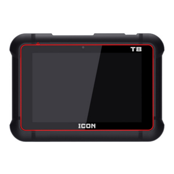
ICON PROFESSIONAL T8 Owner's Manual & Safety Instructions

ICON PROFESSIONAL T8 Owner's Manual & Safety Instructions

Intelligent diagnostic scanner

Advertisement

Owner's Manual & Safety Instructions
Save This Manual
operating, inspection, maintenance and cleaning procedures. Write the product's serial number in the
back of the manual near the assembly diagram (or month and year of purchase if product has no number).
Keep this manual and the receipt in a safe and dry place for future reference.
Email our technical support at: productsupport@harborfreight.com
When unpacking, make sure that the product is intact
and undamaged. If any parts are missing or broken,
please call 1-877-987-4248 as soon as possible.
©
Copyright
2022 by Harbor Freight Tools
No portion of this manual or any artwork contained herein may be reproduced in
any shape or form without the express written consent of Harbor Freight Tools.
Diagrams within this manual may not be drawn proportionally. Due to continuing
improvements, actual product may differ slightly from the product described herein.
Tools required for assembly and service may not be included.
Keep this manual for the safety warnings and precautions, assembly,
Visit our website at: http://www.harborfreight.com
®
. All rights reserved.
PROFESSIONAL T8
INTELLIGENT
DIAGNOSTIC SCANNER
Read this material before using this product.
Failure to do so can result in serious injury.
SAVE THIS MANUAL.
23d
57740

Advertisement

Table of Contents
loading
Need help?

Need help?

Do you have a question about the PROFESSIONAL T8 and is the answer not in the manual?

Questions and answers

Aj Henson
February 13, 2025

How do you use the icon T7 to reset throttle body ,gas peddle, map sensor ,and other settings?

Summary of Contents for ICON PROFESSIONAL T8

  • Page 1 Write the product’s serial number in the back of the manual near the assembly diagram (or month and year of purchase if product has no number). Keep this manual and the receipt in a safe and dry place for future reference. PROFESSIONAL T8 INTELLIGENT DIAGNOSTIC SCANNER 57740 Visit our website at: http://www.harborfreight.com...
  • Page 2: Table Of Contents

    Table of Contents Safety Setup ................2 ................11 Specifications Operation ..............4 ..............18 Overview Maintenance ................ 5 .............. 26 Components and Controls Warranty ........... 8 ..............28 WARNING SYMBOLS AND DEFINITIONS This is the safety alert symbol. It is used to alert you to potential personal injury hazards.
  • Page 3: Safety

    8. Never leave the vehicle unattended 14. Inspect before every use; do not use while running tests. if parts are loose or damaged. 9. Keep a fire extinguisher suitable for gasoline/ 15. Do not place the Scanner on any unstable surface. chemical/electrical fires nearby.
  • Page 4: Specifications

    Specifications Scanner Tablet Operating System Android Processor 4-core 2.0GHz Battery 6300 mAh Memory 4 GB Storage 64 GB Display 6.772 x 4.2745 x 7.9845", IPS Connectivity Wi-Fi: 802.11 b/g/n/ac 2.4G/5G dual frequency Operating Temperature 32°F-113°F Storage Temperature -4°F-158°F Vehicle Communication Interface Working Voltage 9-18 VDC Average Working Current...
  • Page 5: Overview

    Overview OBD II On-Board Diagnostics It is required by the EPA that all 1996 and If the light comes on and stays on, a minor newer vehicles sold in the United States be engine fault condition is occurring and should equipped with an OBD II computer system.
  • Page 6 Control Modules Control Modules are individual computers that operate and monitor different systems in the vehicle. Control Modules vary depending on manufacturer. ID codes are assigned to each Control Module, which are defined by the vehicle’s Communication Protocol. For example, a vehicle may use ID code $7E8 for the PCM and $7E9 for the TCM. Control Module Control Module Definition PCM/ECU...
  • Page 7 Diagnostic Trouble Code A five digit alphanumeric identifier for a fault condition identified by the OBD II system. There are three types of Diagnostic Trouble Codes: 1. Pending - When a fault condition is identified 2. Stored - A Diagnostic Trouble Code is stored during a Drive Cycle, but does not meet when a fault condition has occurred that enough criteria to activate the MIL.
  • Page 8: Components And Controls

    Components and Controls Read the ENTIRE IMPORTANT SAFETY INFORMATION section at the beginning of this manual including all text under subheadings therein before set up or use of this product. Blow Molded Case (1) Scan Tablet (4) Power Cable (5) Stylus (7) WSM (8) USB Cable (2)
  • Page 9 Tablet Top and Front Panel USB Type-C Port USB Type-A (Power/Data) Port (Data) Power On/Off Microphone Front Camera Item 57740 For technical questions, please call 1-877-987-4248. Page 9...
  • Page 10 Vehicle Communication Interface The Vehicle Communication Interface (WSM) is used to read vehicle data and send it to the Tablet via Bluetooth. OBDII Diagnostic Cable Port Power Indicator Vehicle Communication Indicator Scanner Communication Indicator USB Type-C Port OBDII Diagnostic Cable Port: Connects Vehicle Communication Indicator: Flashes when the to vehicle’s OBD II DLC.
  • Page 11: Setup

    Setup Read the ENTIRE IMPORTANT SAFETY INFORMATION section at the beginning of this manual including all text under subheadings therein before set up or use of this product. Charging the Scanner Battery NOTICE: Only use the Power Adapter included with the Scanner. Use of any other adapter will damage the unit.
  • Page 12 Note: To add a new network select Add Network from the list. and then Network & Internet > icon WLAN to configure the Wi-Fi setting. 4. When Connected appears on the screen, it indicates that the unit is properly connected to 2.
  • Page 13 1. Turn on the Scanner Tablet and touch the SETTINGS / SHOP INFORMATION. Icon application on the Home screen. Touch the Settings icon in the Main Menu and then PROFILE to enter the Sign In screen.
  • Page 14 Preferred Brands List will be automatically downloaded in background. Note: Ensure Scanner has strong Wi-Fi connection. 1. Touch Update icon in Main Menu to enter Update screen where a list of diagnostic software will be displayed. 2. All diagnostic software that is upgradable will be selected by default.
  • Page 15 6. On the next prompt, touch Download. Method 2 1. Touch Settings on the Main Menu 3. Select all vehicle manufactuers and log in ICON application. in Preferred Brands List. 4. Type 24-digit number of Subscription Renewal code in input box.
  • Page 16 Vehicle Connections OBD II Vehicle Connection Directly plug the WSM into vehicle’s DLC using supplied OBD II extension cable. WSM Connector OBD II Diagnostics Cable To Vehicle’s DLC Installing the Vehicle Communication Interface Connector 1. Locate the vehicle’s Data Link Connector (DLC). The 16-pin DLC is usually located under the dashboard, within 12 inches of the center of the panel, on the driver’s side of most vehicles.
  • Page 17 3. Use DoIP Cable if you are diagnosing a vehicle using DoIP protocol. Diagnostics Toolbar The diagnostics toolbar contains a number of buttons that enable various procedures. It is displayed at the top of the vehicle diagnostic screens throughout the diagnostic session. Refer to the table below for a brief description of the functions of the diagnostics toolbar buttons.
  • Page 18: Operation

    Operation Basic Operation Chart..........................19 Main Menu ..............................20 Diagnose Diagnostic Preparation ............................Diagnostic System Demonstration ........................All System Code Scan Demo, System Scan Demo, System Selection Demo, Viewing Diagnostic History Demo All System Code Scan Demonstration ....................21 Profile ............................... 23 Settings ..............................
  • Page 19: Basic Operation Chart

    Basic Operation Chart New users should follow the operation chart shown below to get familiar with Scanner operation and functions. To prevent serious injury, read all safety warnings and instructions to ensure proper usage. It is recommended to check for updates on a regular basis to keep current with the latest available software. ** If VINScan is selected to diagnose a vehicle, this step does not apply.
  • Page 20: Main Menu

    Job Menu Turn on the Scanner Tablet and touch the Icon SMOG & OBD2: application on the Home screen to enter the Job Menu. Quick way to check for Diagnostic Trouble Codes and isolate cause for illuminated malfunction indicator lamp (MIL), check monitor status prior to emissions certification testing, verify repairs, and perform a number of other services that are emissions related.
  • Page 21: Diagnostic System Demonstration

    This information can be found in the vehicle’s service manual. 1. Touch the Diagnose icon in the Main Menu to enter the Vehicle Selection page, then touch the DEMO icon to display the following window.
  • Page 22 On-Screen Buttons System Selection Demo • Menu: Return to Main Menu screen. 11. From Test Selection screen, • Exit: Exit the current diagnostic application. touch System Selection. • Tasks: Switch to other in-app 12. Touch desired system. modules running in backstage. 13.
  • Page 23: Profile

    2. Touch the desired selection in the Profile or modify personal information. column on the left to make modifications. 1. Touch the Profile icon in the Job Note: The Username cannot be altered. Menu to enter the Profile screen. Item 57740 For technical questions, please call 1-877-987-4248.
  • Page 24: Settings

    • Files: Automatically adds emissions • Help Module: Touch the Other Modules icon test report and shop information on all in the Job Menu, then touch the Help icon health reports and deletes records and for access to a digital version of this product reports without confirmation or not.
  • Page 25 PLEASE READ THE FOLLOWING CAREFULLY THE MANUFACTURER AND/OR DISTRIBUTOR HAS PROVIDED THE PARTS LIST IN THIS MANUAL AS A REFERENCE TOOL ONLY. NEITHER THE MANUFACTURER OR DISTRIBUTOR MAKES ANY REPRESENTATION OR WARRANTY OF ANY KIND TO THE BUYER THAT HE OR SHE IS QUALIFIED TO MAKE ANY REPAIRS TO THE PRODUCT, OR THAT HE OR SHE IS QUALIFIED TO REPLACE ANY PARTS OF THE PRODUCT.
  • Page 26: Maintenance

    Maintenance There are no user serviceable parts. Have the Scanner serviced by a qualified repair person using only identical replacement parts. This will ensure that the safety of the equipment is maintained. Maintenance TO PREVENT SERIOUS INJURY FROM ELECTRIC SHOCK: Shut down the Scanner Tablet and unplug the Power Adapter from its electrical outlet before inspection, maintenance, or cleaning.
  • Page 27 FCC STATEMENT This device complies with part 15 of the FCC Rules. Operation is subject to the following two conditions: (1) This device may not cause harmful interference, and (2) this device must accept any interference received, including interference that may cause undesired operation. Any changes or modifications not expressly approved by the party responsible for compliance could void the user’s authority to operate the equipment.
  • Page 28: Warranty

    Limited Warranty This ICON product is warranted to the original purchaser to be free from defects in materials and workmanship for a period of one (1) year beginning on the date of purchase (or product receipt, if later). To obtain warranty service, the product or part must be returned to us with proof of purchase (e.g.

This manual is also suitable for:

57740

Table of Contents

Save PDF