Table of Contents
Advertisement
Quick Links
Advertisement
Table of Contents

Related Manuals for Steiel S503 Series

Summary of Contents for Steiel S503 Series
- Page 1 CONTROLLERS S503 Series TECHNICAL MANUAL STEIEL Elettronica S.r.l. – Viale Europa, 24 – 35020 Ponte San Nicolò – PADOVA ITALY Tel. +39 049.8961488 – Fax +39 049.8960184 – www.steiel.it – info@steiel.it Certified Company, according to UNI EN ISO 9001 standards...
- Page 2 WARNINGS This manual is dedicated to the technical personnel responsible of the installation, management and maintenance of the plants. The manufacturer assumes no responsibility for damages or malfunctions occurring after intervention by non-authorized personnel, or not compliant with the prescribed instructions. Before performing any maintenance or repair action, ensure that the system is electrically and hydraulically insulated.
-
Page 3: Table Of Contents
TABLE OF CONTENTS PACKING LIST ............................4 INTRODUCTION AND PRINCIPLE OF OPERATION ................4 DESCRIPTION OF THE FRONT PANEL ....................4 TECHNICAL DATA ..........................5 MECHANICAL DIMENSIONS ........................ 5 ELECTRICAL CONNECTIONS ......................6 START-UP ............................. 7 CONFIGURATION ..........................7 LIST OF PARAMETERS ........................8 MEANING OF PARAMETERS ....................... -
Page 4: Packing List
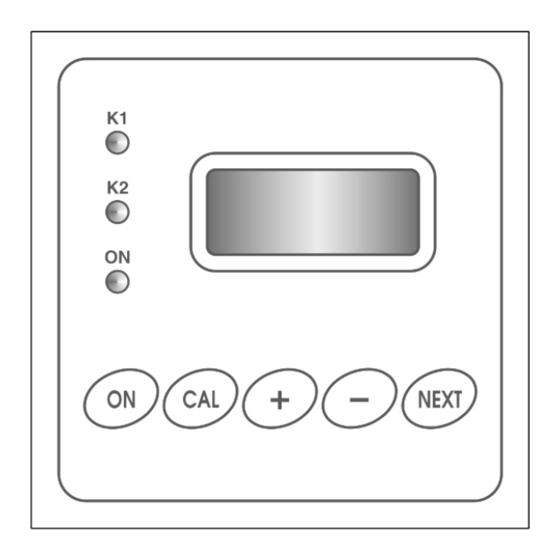
ON button. Alarms and errors are shown directly on the display, and calibration and configuration data are saved into the non-volatile memory for at least 10 years. The S503 series includes several models, for measuring the following parameters: pH / ORP ... -
Page 5: Technical Data
TECHNICAL DATA Common characteristics for all models Power supply 100-240 V~ 50/60 Hz (24V~, 24V- upon request) Power Consumption 5 VA max Protection 5x20 fuse that can be accessed from the rear panel, 24 V~ F 250 mA; 100-240 V~ F 100 mA Display 2-row, alphanumeric LCD (8 digits per row), with backlight Analogue Input... -
Page 6: Electrical Connections
ELECTRICAL CONNECTIONS For correct electrical connections always refer to the rear panel pad printing. The difference among different models is the input signal terminal block (pins 3, 4 and 5), while the remaining connections are the same for all models. ... -
Page 7: Start-Up
For a correct functioning of the device even in bad interference conditions, it is recommended to proceed as follows: a) insert one of the supplied ferrites on the power supply cable as shown in the below picture b) connect the shield of the signal cable to the grounding or to the REF terminal c) insert the second supplied ferrite on the input signal cable as shown in the below picture d) connect RC suppressors (or similar) in parallel with the load (properly dimensioned) e) check the correct grounding connection of the electric cabin that contains the instrument... -
Page 8: List Of Parameters
LIST OF PARAMETERS It is recommended to fill the last column with the values set for your application. Model with pH / ORP or mA input Default PAR. Description value value value value Measure type Reserved 0.00 0.00 0.00 Reserved Working temperature 25 °C Working mode for K1... -
Page 9: Meaning Of Parameters
MEANING OF PARAMETERS PARAMETER 01 (pH / ORP) MEASURE TYPE This model configured and calibrated for pH, ORP or temperature measurements, can be set as follows: 0 = pH-meter, 1 = ORP meter, 2 = thermometer. PARAMETER 01 (Conductivity) CONDUCTIVITY METER TYPE Set this parameter to choose the desired measurement range and cell constant: Cell Range... - Page 10 PARAMETER 03 (pH / ORP, mA input) RESERVED Reserved parameter, for future use. PARAMETER 03 (Conductivity) REFERENCE TEMPERATURE See description of parameter P02. PARAMETER 04 WORKING TEMPERATURE All the S503 models are designed for measuring temperature and use this value for temperature compensation (when required).
- Page 11 PARAMETER 11 MIN THRESHOLD FOR RELAY K2 Minimum threshold value for relay K2 action. If P10=5 (cleaning cycle), this parameter is used to set the pause time (minutes) between two subsequent cleaning cycles. PARAMETER 12 MIN THRESHOLD FOR RELAY K2 Maximum threshold value for relay K2 action.
-
Page 12: Temperature Compensation
(PARAMETER 24) DECIMAL POINT POSITION AND MEASURE UNIT FOR MEAS.1 This parameter is available for models with mA input and allows to set the decimal point position on display and the desired measure unit, accordingly with the following formula: P24 = (Measure unit code x 8) + Decimal point position Codified measure unit are listed in the table below: 1 = pH 2 = mV... -
Page 13: Control Examples
CONTROL EXAMPLES This section includes some configuration examples of control parameters: 1) Acidification control to have approximately pH 7.40 MEASURE TYPE = 0 (pH meter) (P01 = 0) WORKING MODE FOR K1 = 1 (closed when thresholds are exceeded) (P05 = 1) It is recommended to set a narrow threshold window, e.g.: MIN THRESHOLD = 7.30 pH (P06 = 7.30pH) -
Page 14: Errors
ERRORS When an error is detected, the LED ON starts blinking, the mA output provides the fault current value set in P19, and the display shows the corresponding error message, as listed here below: WARNING 1 - RELAY K1 DISABLED No working mode has been configured for K1 output, but the instrument works normally. -
Page 15: Ph Input Specifications
pH INPUT SPECIFICATIONS ELECTRICAL CONNECTIONS FOR pH-METER The signal comes from the electrode through a coaxial cable, with maximum recommended length of 20 meters (for longer cables, please contact the manufacturer). The electrode input is on removable terminal block: connect the coaxial cable core to terminal 4, and the shield to terminal 5 (Note: remove any black conductive plastic between the core and shield of the cable). -
Page 16: Orp Input Specifications
ORP INPUT SPECIFICATIONS ELECTRICAL CONNECTIONS OF ORP-METER The signal comes from the electrode through a coaxial cable, with maximum recommended length of 20 meters (for longer cables, please contact the manufacturer). The electrode input is on removable terminal block: connect the coaxial cable core to terminal 4, and the shield to terminal 5 (Note: remove any black conductive plastic between the core and shield of the cable). -
Page 17: Conductivity Input Specifications
CONDUCTIVITY INPUT SPECIFICATIONS The electronic precision of the conductivity measurements is better than 0.3%, and the repeatability is better than 0.2% FS, without temperature compensation (resistive calibration). The temperature compensation introduces an additional error of 0.3% FS, and is performed through the PT100 input. The temperature sensor may be a probe separated from the conductivity cell (e.g. -
Page 18: Temperature Input Specifications
Note: If you attempt to calibrate using an offset value too different from the range minimum value or a gain value with a too low input signal, the instrument shows the “CALIBRATION ERROR!” message and does not save the calibration data. Conductivity values of KCl (potassium Temp. -
Page 19: Standardized Input Specifications
STANDARDIZED INPUT SPECIFICATIONS ELECTRICAL CONNECTIONS OF THE STANDARDIZED INPUT The signal comes from the transmitter (or transducer) through a 2 or 3-pole cable, that has to be shielded if longer than 20 meters. Connections are made on removable terminal block as follows: 1.
Need help?
Do you have a question about the S503 Series and is the answer not in the manual?
Questions and answers