Advertisement
JATCO Environmental Protection Tank
*INSTRUMENTATION GAS IS MANDATORY FOR SUPPLY GAS*
The JATCO Environmental Tank must be installed at a level which will allow the waste
liquids to be disposed of to gravity flow into the tank.
IMPORTANT: The top of the tank must be below the level of waste liquids to be
received.
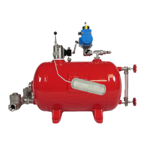
Inlet and the outlet check valves are both teed from the same port near the bottom of the
tank (end opposite the sight glass). When facing this end, the inlet check valve is on the
left (A) and the outlet check valve is on the right (B).
The discharge should be piped directly to the storage tank that is to receive the waste liquid.
The discharge may be teed into an existing flow line, provided that a high-pressure check
valve (1000 psi) is installed to prevent high pressure from returning to the discharge check
valve on the JATCO tank.
The tank supply gas must have adequate
pipe for the tank supply gas plumed as close to the tank as possible. Then reduce down to the
tubing connections (C) and (J) on the JATCO tank.
This application requires two separate supply gas pressures. First supply gas pressure is
connected to the bottom inlet of the micro valve (C) this gas pressure must meet 70 psi
and not exceed 100 psi. Second supply gas pressure is connected to the 3-way ball valve
(J) this gas pressure must not exceed 100 psi for normal operation. No pressure regulator
is provided.
Manual dump plunger (F) and gauge cock knobs are removed for shipping.
Manual Dump Plunger (F): Install in ⅛" NPT hole in top of valve body.
Note: The gland nut should be finger tight only.
Depressing the manual dump plunger (F) allows the operator to check function of the float
and micro valve. When the plunger is depressed, the tank will cycle once and return to the
automatic operation. The plunger button should be returned to the extended position.
3-way ball valve (G) is vented thru ½" NPT port (H).
Liquid levels in the JATCO tank may be observed in the sight glass (I) furnished as standard
equipment.
th
244 N.W. 111
St.
•
Installation Instructions
J-5000-100 ABV SS
volume
Oklahoma City, Oklahoma 73114 •
and pressure. For best operation use 1"
405/755-4100 • 405/755-4101 Fax
Advertisement
Table of Contents

Related Manuals for Jatco J-5000-100 ABV SS


Summary of Contents for Jatco J-5000-100 ABV SS
- Page 1 The plunger button should be returned to the extended position. 3-way ball valve (G) is vented thru ½” NPT port (H). Liquid levels in the JATCO tank may be observed in the sight glass (I) furnished as standard equipment.
- Page 2 *INSTRUMENTATION GAS IS MANDATORY FOR SUPPLY GAS* Listed below are a series of steps to follow if the JATCO tank fails to dump properly. Be sure there is an adequate supply of volume and gas pressure (70-100 psi), to the inlet connection on the micro valve (C), and (100 psi max) to the 3-way ball valve supply (J).
- Page 3 J-5000-100 ABV SS A. Inlet Check Valve 1" NPT JM5005 B. Discharge Check Valve 1" NPT JM5005 C. Supply Gas Inlet ½" NPT Compression (70-100 psi) 21 ¼” D. ¼" NPT Micro Valve JM5001 SS E. Pressure Relief Valve JM5002-100 F.
- Page 4 The sole liability and exclusive remedy is limited to the repair or replacement, at the option of JATCO, Inc., of the product, or any parts thereof, which upon examination by JATCO, Inc., disclose to its satisfaction defects due to faulty material or poor workmanship, and which defects are reported to JATCO, Inc., in writing, during the warranty period.
- Page 5 JATCO, Inc. to notify any person of such revisions or changes. It shall be the user’s responsibility to determine whether any changes or revisions to this manual have been made.
Need help?
Do you have a question about the J-5000-100 ABV SS and is the answer not in the manual?
Questions and answers