Table of Contents
Advertisement
Quick Links
TD'S DISK CONTROLLER
TD'S DISK CONTROLLER
TD'S DISK CONTROLLER
Preliminary Installation and Operation Manual
Preliminary
Lance Design / 27 Fairview Avenue / Ridgefield, Connecticut 06877
Lance Design / 27 Fairview Avenue / Ridgefield, Connecticut 06877
Lance Design / 27 Fairview Avenue / Ridgefield, Connecticut 06877
TDC-100B
Software Version 1.1
Tel: 203-894-8206
www.lancedesign.net
Advertisement
Table of Contents

Summary of Contents for Lance Design TDC-100B
- Page 1 Preliminary Preliminary Installation and Operation Manual Software Version 1.1 Lance Design / 27 Fairview Avenue / Ridgefield, Connecticut 06877 Lance Design / 27 Fairview Avenue / Ridgefield, Connecticut 06877 Lance Design / 27 Fairview Avenue / Ridgefield, Connecticut 06877 Tel: 203-894-8206...
- Page 2 Lance Design, and also that the equipment is returned to Lance Design with prior authorization.
-
Page 3: Table Of Contents
Table of Contents Quick Operation Guide ………………………………… Page 4 General Description …………………………………… Page 7 Control Panel Description ……………………………. Page 7 Menu Items …………………………………………….. Page 9 General Operation …………………………………….. Page 14 Trigger Function Numbers …………………………… Page 15 Multi-Device Control Rules …………………………… Page 17 Multi-Point Loops ………………………………………... -
Page 4: Quick Operation Guide
The display will say ‘CLR To Clear All!’. If you press the CLR key (while holding down the above three buttons) the TDC-100B will start clearing registers at the current register, and ascending until you either press the STOP button, or it reaches the last register (299). - Page 5 Quick Operation Guide - continued To recall an in or out time to the display, press FCN, then MARK IN or MARK OUT. The corresponding time value will be recalled to the display and the scratchpad register, so you can do arithmetic with it if desired (add and subtract). If you ‘double-click’...
- Page 6 If the Pbus data is incorrectly formatted (invalid command) a ‘Pbus Format Error’ message will be displayed. Note that this menu item is turned off each time the TDC-100B is powered up. To Use USB Port for Cue/Menu Offline Storage see the USB section on page 21...
-
Page 7: General Description
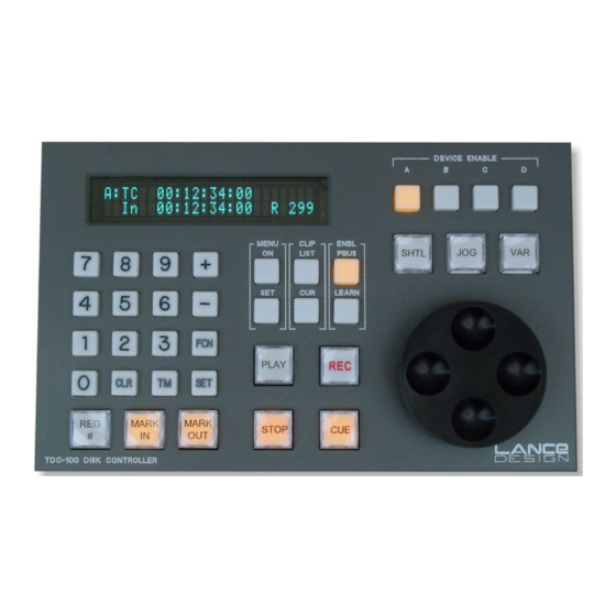
GENERAL DESCRIPTION The Lance Design TDC-100B is designed to provide control of multiple channels of video disk recorder(s) or other devices via P-Bus II interface to Grass Valley Group, Sony, or other production switchers. This combination allows the user to do the following: 1) Mark playback inpoints when learning an emem effect on the switcher. - Page 8 REG# - used to select the active register from the 300 available registers. Press this key (it lights), and enter a 3-digit register number on the keypad. The active register number is displayed in the lower right corner of the display as ‘R 299’, for example.
-
Page 9: Menu Items
DEVICE ENABLE (A,B,C,D) - four device enable keys corresponding to the four control ports on the TDC-100B. Any lighted key is enabled, and will be sent all transport commands and PBUS commands. If more than one is enabled, the one that is flashing is the currently-displayed one. - Page 10 CLIP LIST MODE (INT / EXT) This item selects the clip list mode that the TDC-100B uses to access the list of available clips on the ddr. The INT mode builds the list within the TDC-100B, and will operate with any ddr which supports Odetics protocol. In this mode the list is limited to 99 clips.
- Page 11 This would allow you to rehearse your effects without modifying the registers. These menu items are set to ‘CHECKED’ each time the TDC-100B is powered up, and this is the setting that should normally be used.
- Page 12 This item is generally set to LOW. SWITCHER TYPE (GVG / SONY) Selects type of production switcher TDC-100B is used with. Affects the trigger function numbers (swaps functions 0 and 1. See page 15) P-BUS PARITY (NONE/ODD/EVEN) Sets parity mode of P-bus port.
- Page 13 TDC FIRMWARE VERSION: Displays the installed firmware in the TDC frame. This manual applies to TDC-100B version 1.0 firmware. FRAME IP ADDRESS: Displays the IP address of the TDC-100B Frame. The Panel IP is this number plus 1. These IP combinations are selected by the first three sections of the dip switches on each unit (panel and frame).
-
Page 14: General Operation
GENERAL OPERATION WHAT IS A REGISTER? In this controller, a register refers one set of these items: Device A Inpoint Device A Outpoint Device A Clip Name (if enabled) Device B Inpoint Device B Outpoint Device B Clip Name (if enabled) Device C Inpoint Device C Outpoint Device C Clip Name (if enabled) -
Page 15: Trigger Function Numbers
When the switcher sends a TRIGGER, all enabled machines are sent a command corresponding to the ‘Function Number’ specified for that trigger in the switcher menu. The function numbers are as follows: When TDC-100B is in the GVG (Grass Valley) mode: Function Number Command... - Page 16 an effect in Emem 25 for example, register 025 will be recalled on the TDC when you recall that effect. If you send a Trigger 11 from within that effect, register 125 will be recalled. If you send a Trigger 12 register 225 will be recalled. Note that these recalls are just like normal register recalls, in that they affect all channels.
-
Page 17: Multi-Device Control Rules
MULTI - DEVICE CONTROL RULES This section describes how the controller handles various combinations of multiple machines and device enable numbers The controller front panel controls enabled machines; ones with lighted Device Enable buttons. Some front panel functions affect only the Displayed machine - the one whose letter is in the upper left corner of the display. -
Page 18: Multi-Point Loops
Using Auto-Dub Feature to Transfer Material From VTR to Disk The vtr Auto-Dub feature is not supported in firmware version 1.1 for the TDC-100B The Record Trim menu item is still in place, but has no function at this time. -
Page 19: Usb Port Operation
The cue files (.td2) and menu files (.tds) are stored on a standard USB flash drive ('thumb drive') in DOS format text file. The flash drive must be formatted in the FAT32 format. The TDC-100B is not capable of formatting the drives. Drives formatted in FAT32 format are compatible with both Windows and Mac operating systems. - Page 20 The eight main menu functions are: 1- Read .TD2 File to TDC This is used to read cues from a file on the USB drive into the TDC-100B Registers. Once this function is selected, you'll be able to select the file name from all available .td2 files.
- Page 21 This function provides that capability. The clock will continue to run for about one week when the TDC-100B is powered off, so it will maintain accurate time so long as the TDC-100B is powered up from time to time. The current time will be displayed on the top line, and you can enter a time on the bottom line with the numeric keypad.
-
Page 22: Installation
INSTALLATION AND CONNECTIONS TDC-100B Frame, Rear Panel The TDC-100B consists of two pieces: the rack-mounted electronics frame (1RU) and the control panel. They are interconnected with standard Ethernet (100baseT). Neither the frame nor the panel is compatible with the older TDC-100s which use RS-422 communication between the units. - Page 23 The data format for the P-Bus input is RS-422, 38.4K Baud. Parity may be selected in the TDC-100B menu (Item 30) to be even, odd, or none. This parity selection must match the data being sent from the switcher. The default setting is odd parity.
-
Page 24: Setting Ip Addresses
All of the IP addresses are local subnet addresses. As far as the TDC-100B is concerned, any pair of addresses may be used, so long as they don’t conflict with another device on the same network. - Page 25 IP ADDRESS TABLE Address Frame Dipswitch Frame IP address Panel IP address Pair Setting 10.30.1.80 10.30.1.81 10.30.1.82 10.30.1.83 172.30.1.80 172.30.1.81 172.30.1.82 172.30.1.83 192.168.1.80 192.168.1.81 192.168.1.82 192.168.1.83 192.168.1.180 192.168.1.181 192.168.1.182 192.168.1.183 The subnet mask is set to 255.255.255.0 in every case. Important Note: The settings of the first three sections of the dipswitch on the panel (near the Ethernet connector) and the first three sections of the switch on the rear of the frame must match for the panel and frame to communicate.
-
Page 26: Connector Pinouts
The P-bus port on the TDC-100B is listen only, as of firmware version 1.1. The data is RS-422, 38.4K baud, and the parity is selectable in the TDC-100B menu. Parity is normally selected to be Odd. Parity selected must match the switcher, or a ‘Parity Error’... -
Page 27: Gpi Inputs And Outputs
RS232 INTERFACE CABLE (FOR PC UPLOAD/DOWNLOAD OF CUES) TDC-100B PC COM PORT RS232/GPI DB-15 MALE DB-9 FEMALE PIN 1 SIGNAL GROUND PIN 5 PIN 2 DATA FROM PC TO TDC-100B PIN 3 PIN 3 DATA FROM TDC-100B TO PC PIN 2... - Page 28 Notes:...
Need help?
Do you have a question about the TDC-100B and is the answer not in the manual?
Questions and answers