Sign In
Upload
Download
Table of Contents
Contents
Add to my manuals
Delete from my manuals
Share
URL of this page:
HTML Link:
Bookmark this page
Add
Manual will be automatically added to "My Manuals"
Print this page
×
Bookmark added
×
Added to my manuals
Manuals
Brands
Mustang Manuals
Compact Loader
2044
Operator's manual
Mustang 2044 Operator's Manual
Skid-steer loader
Hide thumbs
1
2
Table Of Contents
3
4
5
6
7
8
9
10
11
12
13
14
15
16
17
18
19
20
21
22
23
24
25
26
27
28
29
30
31
32
33
34
35
36
37
38
39
40
41
42
43
44
45
46
47
48
49
50
51
52
53
54
55
56
57
58
59
60
61
62
63
64
65
66
67
68
69
70
71
72
73
74
75
76
77
78
79
80
81
82
83
84
85
86
87
88
89
90
91
92
93
94
95
96
97
98
99
100
101
102
103
104
105
106
107
108
109
110
page
of
110
Go
/
110
Contents
Table of Contents
Troubleshooting
Bookmarks
Advertisement
Table of Contents
1
Table of Contents
2
Introduction
3
Safety
4
Controls and Safety Equipment
5
Operation
6
Service
7
Troubleshooting
8
Maintenance
9
Specifications
10
Torque Specifications
11
Warranty
12
Index
Download this manual
®
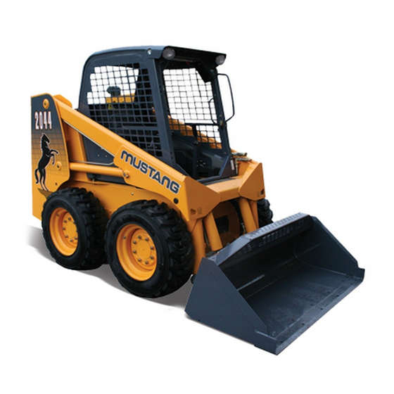
2044
2054
MUSTANG
SKID-STEER
LOADER
OPERATOR'S
MANUAL
#917099/GP0310
®
Mustang Manufacturing Company, Inc.
P.O. Box 179
West Bend, WI 53095-0179 USA
Table of
Contents
Previous
Page
Next
Page
1
2
3
4
5
Advertisement
Table of Contents
Need help?
Do you have a question about the 2044 and is the answer not in the manual?
Ask a question
Questions and answers
Related Manuals for Mustang 2044
Compact Loader Mustang 2054 Operator's Manual
Skid-steer loader (110 pages)
This manual is also suitable for:
2054
Table of Contents
Save PDF
Print
Rename the bookmark
Delete bookmark?
Delete from my manuals?
Login
Sign In
OR
Sign in with Facebook
Sign in with Google
Upload manual
Upload from disk
Upload from URL


Need help?
Do you have a question about the 2044 and is the answer not in the manual?
Questions and answers