
Summary of Contents for Allwinner MINI507
- Page 1 MINI507 Reference User Manual V1.202308 Boardcon Embedded Design www.armdesigner.com...
- Page 2 Your Idea Customize the embedded system based on 1. Introduction 1.1. About this Manual This manual is intended to provide the user with an overview of the board and benefits, complete features specifications, and set up procedures. It contains important safety information as well. 1.2.
-
Page 3: Table Of Contents
1.1 Summary ............................. 3 1.2 Features ............................3 1.3 Block Diagram..........................6 1.4 Mini507 specifications ........................7 1.5 Mini507 PCB Dimension ......................8 1.6 MINI507 Pin Definition ......................... 8 1.7 Development Kit (EMT507) ......................14 2 Hardware Design Guide ........................15 2.1 Peripheral Circuit Reference ...................... -
Page 4: Mini507 Introduction
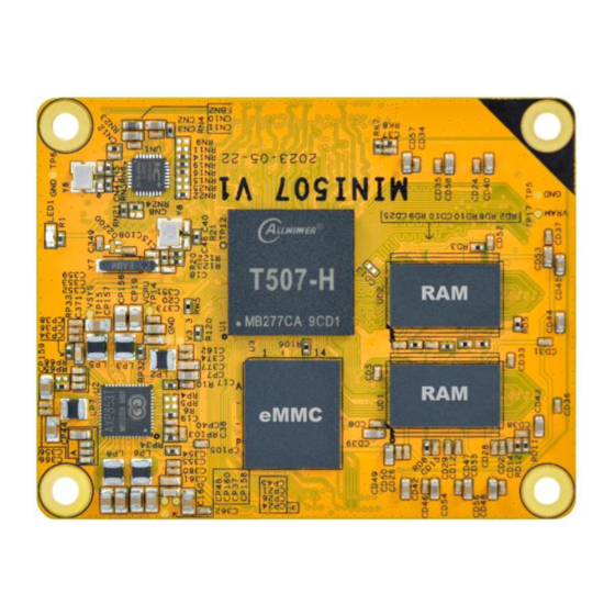
1 MINI507 Introduction 1.1 Summary The MINI507 system-on-module is equipped with Allwinner’s T507 quad-core Cortex-A53, G31 MP2 GPU. It is designed specifically for the smart devices such as industrial controller, IoT devices, digital cluster and automotive devices. The high performance and low power solution can help customers to introduce new technologies more quickly and enhance the overall solution efficiency. - Page 5 Your Idea Customize the embedded system based on - Three I2S/PCM interface - Support up to 8-CH DMIC - One SPDIF input and output • - Four USB 2.0 interfaces - One USB 2.0 OTG, and three USB hosts • Ethernet - Support two Ethernet interface - One 10/100M PHY on CPU Board...
- Page 6 Your Idea Customize the embedded system based on - up to 24/100MHz output frequency - Minimum resolution is 1/65536 • Interrupt Controller - Support 28 interrupts • 3D Graphics Engine - ARM G31 MP2 supply - Support OpenGL ES 3.2/2.0/1.1, Vulkan1.1, Open CL 2.0 standard •...
-
Page 7: Block Diagram
Your Idea Customize the embedded system based on 1.3 Block Diagram 1.3.1 T507 Block Diagram... -
Page 8: Mini507 Specifications
Your Idea Customize the embedded system based on 1.3.2 Development board (EMT507) Block Diagram 1.4 Mini507 specifications Feature Specifications Quad-core Cortex-A53 2GB DDR4 (up to 4GB) eMMC FLASH 8GB (up to 64GB) Power DC 5V LVDS Dual CH up to 4-Lane... -
Page 9: Mini507 Pcb Dimension
Customize the embedded system based on 5-CH 2-CH UART 5-CH, 1-CH(DEBUG) 6-CH ADC IN 4-CH Board Dimension 51 x 65mm 1.5 Mini507 PCB Dimension --Top View-- 1.6 MINI507 Pin Definition Signal Description Alternate functions IO Voltage MDI-RN 100M PHY MDI 1.8V... - Page 10 Your Idea Customize the embedded system based on Signal Description Alternate functions IO Voltage Ground LVDS0-CLKN/LCD- LVDS or RGB display interface PD7/EINT7/TS0-D3 3.3V LVDS0-D3N/LCD-D LVDS or RGB display interface PD9/EINT9/TS0-D5 3.3V LVDS0-CLKP/LCD- LVDS or RGB display interface PD6/EINT6/TS0-D2 3.3V LVDS0-D3P/LCD-D LVDS or RGB display interface PD8/EINT8/TS0-D4 3.3V...
- Page 11 Your Idea Customize the embedded system based on Signal Description Alternate functions IO Voltage LCD-D22 RGB display interface PD22/EINT22 3.3V LCD-D21 RGB display interface PD21/EINT21 3.3V LCD-D23 RGB display interface PD23/EINT23 3.3V LCD-PWM PWM0 PD28/EINT28 3.3V LCD-HSYNC RGB display interface PD26/EINT26 3.3V Ground...
- Page 12 Your Idea Customize the embedded system based on Signal Description Alternate functions IO Voltage MCSI-CLKN MIPI CSI differential clock N 1.8V MCSI-D1N MIPI CSI differential data 1N 1.8V MCSI-CLKP MIPI CSI differential clock P 1.8V MCSI-D1P MIPI CSI differential data 1P 1.8V Ground MCSI-D0N...
- Page 13 Your Idea Customize the embedded system based on Signal Description Alternate functions IO Voltage PE17 CSI0-D13 PE-EINT18 3.3V CSI0-D4 PE-EINT9 3.3V SDC0-DET SD card detection PF6/EINT6 3.3V CSI0-VSYNC PE-EINT4 3.3V Ground CSI0-HSYNC PE-EINT3 3.3V SDC0-D0 SD Data0 PF1/EINT1 3.3V CSI0-MCLK PE-EINT2 3.3V SDC0-D1...
- Page 14 Your Idea Customize the embedded system based on Signal Description Alternate functions IO Voltage RGMII-TXCTL RMII-TXEN/UART3CTS/PWM2 PI12/EINT12/TS0-D3 3.3V BT-PCM-DIN H-I2S2-DO1/DIN0/AC-ADCX PG14/EINT14 1.8V RGMII-TXD3 UART2-RTS/I2C1-SCL PI7/EINT7/TS0SYNC 3.3V BT-UART-RTS UART1-RTS/PLL-LOCK-DBG PG8/EINT8 1.8V RGMII-TXD2 UART2-CTS/I2C1-SDA PI8/EINT8/TS0DVLD 3.3V BT-UART-CTS UART1-CTS/AC-ADCY PG9/EINT9 1.8V RGMII-TXD1 RMII-TXD1/UART3TX/I2C2SCL PI9/EINT9/TS0-D0 3.3V BT-UART-RX...
-
Page 15: Development Kit (Emt507)
Your Idea Customize the embedded system based on Signal Description Alternate functions IO Voltage Ground DCIN Main Power input 3.4V-5.5V DCIN Main Power input 3.4V-5.5V DCIN Main Power input 3.4V-5.5V DCIN Main Power input 3.4V-5.5V DCIN Main Power input 3.4V-5.5V DCIN Main Power input 3.4V-5.5V... -
Page 16: Hardware Design Guide
Your Idea Customize the embedded system based on 2 Hardware De sign Guide 2.1 Peripheral Circuit Reference 2.1.1 External Power 2.1.2 Debug Circuit... - Page 17 Your Idea Customize the embedded system based on 2.1.3 USB OTG Interface Circuit 2.1.4 HDMI Interface Circuit...
-
Page 18: Power Tree
Your Idea Customize the embedded system based on 2.2 Power Tree 2.3 B2B connector for carrier board DF40C-100DS-0.4V... -
Page 19: Product Electrical Characteristics
Your Idea Customize the embedded system based on 3 Product Electrical Characteristics 3.1 Dissipation and Temperature Symbol Parameter Unit DCIN System Voltage System IO VSYS_3V3 3.3-5% 3.3+5% Voltage Peripheral DCDC6_3V3 3.3-5% 3.3+5% Voltage Camera IO ALDO5 Voltage Camera Core BLDO5 Voltage DCIN Idcin...
Need help?
Do you have a question about the MINI507 and is the answer not in the manual?
Questions and answers