Table of Contents
Advertisement
Quick Links
EN
IST-1516.CE01.02
File: IST-1516.CE01.02_CE516-EN (04.03.2021).docx
GAS CONTROL UNIT
CITY
CE516P
Max no.16 Gas Detectors on RS485 BUS
with proprietary protocol
USER MANUAL
TECNOCONTROL S.r.l.
Via Miglioli, 47 20054 SEGRATE (MI) Italy- Tel. (+39) 02 26922890 - Fax (+39)02 2133734
http:
www.cpftecnogeca.com
e-mail:
info@tecnocontrol.it
Advertisement
Table of Contents

Summary of Contents for Techno Control CITY CE516P
- Page 1 IST-1516.CE01.02 File: IST-1516.CE01.02_CE516-EN (04.03.2021).docx GAS CONTROL UNIT CITY CE516P Max no.16 Gas Detectors on RS485 BUS with proprietary protocol USER MANUAL TECNOCONTROL S.r.l. Via Miglioli, 47 20054 SEGRATE (MI) Italy- Tel. (+39) 02 26922890 - Fax (+39)02 2133734 http: www.cpftecnogeca.com e-mail: info@tecnocontrol.it...
-
Page 2: Information And Warnings Of Use
IST-1516.CE01.02 CE516P / User Manual Pag. 2/50 Please read and keep care of this manual and the manual of installed sensors too. All documentation relating to gas detection plant should be preserved, because it contains the procedures to be used during the routines verification and / or during the periodic calibration. -
Page 3: Table Of Contents
IST-1516.CE01.02 CE516P / User Manual Pag. 3/50 SOMMARIO INFORMATION AND WARNINGS OF USE NOTES FOR READING INSTRUCTION PRODUCT DESCRIPTION Fig.1 – CE516P - Wall mount housing Fig.2 - Eg installation with TS482 series detectors. CONTROL UNIT INSTALLATION Fig 3 – CE516P Dimensions and Template for wall mounting. OPEN –... - Page 4 IST-1516.CE01.02 CE516P / User Manual Pag. 4/50 LOGIC INPUT – DETAILS: ZONES ZONES - ENABLE/DISABLE (Level 1): ZONES - CONFIGURE (Level 2): Description of items related to the Zone: Description of the items relating to the outputs: ZONES-DELETE (Level 2): ZONES-MODIFY (Level 2): ZONES-DETAILS: EVENTS...
-
Page 5: Product Description
IST-1516.CE01.02 CE516P / User Manual Pag. 5/50 PRODUCT DESCRIPTION Fig.1 – CE516P - Wall mount housing SD-CARD Max No.16 Detectors No.2 RS485 proprietary Bus COM1 max No.8 Detectors COM2 max No.8 Detectors No.5 or No.9 Relay No.1 Logic Input Mains Supply 90÷264 VAC Internal Batteries (optional) No.1 RS485 (COM3)Modbus (with ES415 optional card) - Page 6 IST-1516.CE01.02 CE516P / User Manual Pag. 6/50 SE301 SIRENA / SIREN CE516P RILEVATORI (es.TS482) / DETECTORS (e.g.TS482) / SONDES (par ex.TS482) COM1 RS485 Lunghezza MAX cavi MAX cable lenght / Longueur de câble maxi Ingresso Logico AUX (es. PULSANTE) COM2 RS485 AUX Logic input (eg.
- Page 7 IST-1516.CE01.02 CE516P / User Manual Pag. 7/50 The Control Unit can store the Events: The system can store up to 100 events comprising Alarms, Faults, Power ON, Mains blackout and Resetting, that can be re-called at any time. The Control Unit has an SD-CARD slot, it can be used for: Future updates of the Control Unit firmware.
-
Page 8: Control Unit Installation
IST-1516.CE01.02 CE516P / User Manual Pag. 8/50 CONTROL UNIT INSTALLATION THE FOLLOWING INSTRUCTIONS DESCRIBES ALL THE CONTROL UNIT SYSTEM SETUP PROCEDURES AND THE INSTALLATION PROCEDURES TO BE EXECUTED ONLY BY AUTHORISED AND EXPERIENCED STAFF WARNING: The unit is to be installed in an area protected from direct sunlight and rain. -
Page 9: Electrical Connections
IST-1516.CE01.02 CE516P / User Manual Pag. 9/50 ELECTRICAL CONNECTIONS The electrical connections should be executed all on the housing base. The details of the connections to the mains, the two batteries, the AUX input and relay output R9 are illustrated in Figure While the details of the connections to the sensors and the other outputs are illustrated... -
Page 10: Power Connection
IST-1516.CE01.02 CE516P / User Manual Pag. 10/50 Power connection The installation must include a power line protection device. To the mains line, a bipolar disconnecting switch dedicated for the gas detection system. The device, clearly identified, must act only on Phase and Neutral, but not on the Earth. -
Page 11: Connection With Gas Detectors (Sensors)
IST-1516.CE01.02 CE516P / User Manual Pag. 11/50 Connection with Gas Detectors (Sensors) Please always refer to the specific instructions supplied with detectors. Please note that the Control Unit has a card with no.4 outputs. An ES414 board can be installed to have a total of 9 outputs. In the diagrams, for simplicity, they are always indicated with all the Outputs. - Page 12 IST-1516.CE01.02 CE516P / User Manual Pag. 12/50 If alternatively, separate power supplies are used from the control unit, we recommend the use of type feeders SELV (Safety Extra Low-Voltage) and it will be necessary to use a third cable gland for the power supply.
-
Page 13: Detector Address : Dip-Switch Set-Up
IST-1516.CE01.02 CE516P / User Manual Pag. 13/50 LED Rx/Tx FUSE 2A (5x20) COM 1 LED Rx/Tx COM 2 Main Board Input Outputs board AUX and (Relays 1÷4) Outputs Relay 9 RS485 BUS INPUT BOARD Position Expansion board COM 2 - RS485 COM 1 - RS485 ES414 (Relays 5÷8) N T L... - Page 14 IST-1516.CE01.02 CE516P / User Manual Pag. 14/50 IMPORTANT ADVICE: before installing and configuring the control unit, evaluate how many alarm devices are connected to the relays to determine how many relays are needed and how they should act. Please see in SENSORS> Configure>...
-
Page 15: Expansion Board Es415 - Modbus
IST-1516.CE01.02 CE516P / User Manual Pag. 15/50 ® Expansion Board ES415 - Modbus The connection to a monitoring system via Modbus RTU binary protocol (COM3) is carried on the optional expansion board ES415 (PC-Card Modbus output). The ES415 board is mounted on the main board, placed in housing cover. (See Figure 11). -
Page 16: Use Of The Control Unit
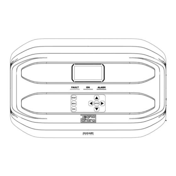
IST-1516.CE01.02 CE516P / User Manual Pag. 16/50 USE OF THE CONTROL UNIT Display Ecran Tastiera Keyboard Clavier Fig.12 – CE516P Keyboard Keyboard The keyboard is backlit. To save energy, the brightness is reduced to half after 10 seconds of non-use. Can only be used on the main screen, it is used to reset the latched outputs to normal operation, but only if the Sensor or Zone or Input has returned from the alarm condition. -
Page 17: Screens 'Enable
IST-1516.CE01.02 CE516P / User Manual Pag. 17/50 Screens 'Enable ...', 'Disable ...', 'Copy ...', 'Delete ...', 'Settings-> Date & Time': Pressing the first time, key, the number is displayed in its field (deleting any existing number), and the next digits will be always inserted to the right of the number. Example: to enter the number “12”, press once, then press PARAMETER... - Page 18 IST-1516.CE01.02 CE516P / User Manual Pag. 18/50 If the control unit, had lost the date and time, due to a malfunction or discharge of the clock backup battery, screen will be displayed for entering updated values (The unit's safety functions are guaranteed, except those involving the use of date that will be wrong). By changing these parameters, see below, the section SETTINGSDATE and TIME.
- Page 19 IST-1516.CE01.02 CE516P / User Manual Pag. 19/50 Indicates the output number (Relay), corresponding respectively to: Threshold (AL1) Threshold (AL2) Threshold (AL3) FAULT. Value 0 (zero) indicates, at that threshold, the output not been assigned, while the highlighted value indicates that output relay is currently active (alarm). The values are real time updated.
-
Page 20: Main Menu
IST-1516.CE01.02 CE516P / User Manual Pag. 20/50 MAIN MENU CE516 The Control Unit is provided with a main menu from which you can 1 RESET manage all of its functions. 2 RESERVED The name of each line indicates the thematic area on which we can take 3 SENSORS action, by accessing the corresponding submenus. -
Page 21: Reset
IST-1516.CE01.02 CE516P / User Manual Pag. 21/50 RESET The RESET item in the main menu, performs the same function as RESET key, reset the latched outputs to normal operation, but only if the Sensor or Zone or Logic Input has returned from the alarm condition. If there are active alarms, outputs configured as Silenceable (e.g. -
Page 22: Configure Sensors (Level 2)
IST-1516.CE01.02 CE516P / User Manual Pag. 22/50 SENSOR If the procedure is correct, a window warns that the operation has been successful. Then the screen returns to the start of the Enable / Disable N. 1 management ENABLE IMPORTANT: Before starting the setup, decide how many and which outputs are to be used (relay) according to the type, to the requested operation and the number of actuators installed and in which the alarm levels are associated. - Page 23 IST-1516.CE01.02 CE516P / User Manual Pag. 23/50 Chosen model, will load its configuration. PRECONF. SENS. With you can scroll through the various items. Press ENTER SENSOR N. on the item, it is only highlighted the value, editable with MODEL: TS482KM With you move from one field to the other in the same row TAG:...
-
Page 24: Description Of Items Related To The Preconfigured Sensor
IST-1516.CE01.02 CE516P / User Manual Pag. 24/50 name indicated in the tables (annex B) of the standard IEC/EN The gas name displayed is the 1 60079-20-1 Explosive Atmospheres - Part 20-1: Classification of gases and vapours - Test methods and data. -
Page 25: Description Of The Items Relating To The Outputs
IST-1516.CE01.02 CE516P / User Manual Pag. 25/50 PARKING EN: The alarm levels should be set so increasing, i.e. SENSOR SCALE ≥ ALARM 3 ≥ ALARM 2 ≥ ALARM 1 ≥ FAULT. In this case, the first two levels of alarm representing a value obtained with a time average between 5 and 60 min. -
Page 26: Configure - Search Sensor
IST-1516.CE01.02 CE516P / User Manual Pag. 26/50 The function latched, cannot be used simultaneously with DELAY OFF or TIME ON. For safety, if the parameter latched, was set YES, the parameters DELAY OFF and TIME ON, will be automatically set to Zero. Then at the end of the screen, SAVE appears. -
Page 27: Sensors-Copy (Level 2)
IST-1516.CE01.02 CE516P / User Manual Pag. 27/50 It is the number of Sensors not present, available for future extensions or not identified ABSENT because they are not connected correctly or with the wrong address (e.g. Same as other sensors). SENSORS-COPY (Level 2): COPY This item allows you to copy the configuration of a sensor to another SENSOR N. -
Page 28: Sensors-Details
IST-1516.CE01.02 CE516P / User Manual Pag. 28/50 SENSORS-DETAILS: To see the parameters of an already configured sensor, press on the relevant item. ENTER Once the desired Sensor number has been chosen, the items are as in THRESHOLD_1 : the configuration of a Sensor. You can scroll through them with OUTPUT_1 N. -
Page 29: Logic Input - Delete (Level 2)
IST-1516.CE01.02 CE516P / User Manual Pag. 29/50 Then at the end of the screen, move to SAVE to save the configuration entered. By pressing the confirmation window will appear. Press ENTER INPUT N. 1 again to confirm, or press to go back. ENTER CONFIGURED After confirming, a window warns that the operation was successful. -
Page 30: Zones - Configure (Level 2)
IST-1516.CE01.02 CE516P / User Manual Pag. 30/50 ZONES - CONFIGURE (Level 2): In the ZONES submenu, press on the item for CONFIGURE to ENTER ZONES CONFIG. configure the ZONE. ZONE N. On the screen, pressing , then using you choose the ENTER number of the ZONE to be configured. -
Page 31: Zones-Modify (Level 2)
IST-1516.CE01.02 CE516P / User Manual Pag. 31/50 After choosing, choose whether to act on a single ZONE (1 line) or on ZONE a group of ZONES (2 line) and confirming with the window, it will ENTER N. 1 warn you that the operation was successful. DELETED Then the screen returns to the beginning of the CANCEL management. -
Page 32: Settings
IST-1516.CE01.02 CE516P / User Manual Pag. 32/50 EVENTS - ALL Generic events, which can be viewed from the menu, can have 4 states: POWER ON (the control unit has been switched on). MAINS YES (the control unit is mains power supply, only if batteries are installed). NETWORK NO (the control unit is powered only by batteries, if installed). -
Page 33: Settings-Date And Time (Level 1)
IST-1516.CE01.02 CE516P / User Manual Pag. 33/50 SETTINGS-DATE and TIME (Level 1): To change date and time press on the item. With ENTER TIME change the values, with you move from one field to 10: 15 another. Then move to the word “SAVE” and press . -
Page 34: Settings-Info
IST-1516.CE01.02 CE516P / User Manual Pag. 34/50 NOTE: The value of a "NOT CONFIGURED" sensor is always 0. Since the submitted values, are the word (16-bit signed), to represent decimal numbers, certain values are multiplied by a factor determined by the number of decimal places specified in the configuration of the sensor. -
Page 35: Disable Level
IST-1516.CE01.02 CE516P / User Manual Pag. 35/50 If an incorrect password was entered, the window alerts you of the error STOP INCORRECT PASSWORD and return to the screen ENTER PASSWORD DISABLE LEVEL This item allows you to disabling the relative access level. ENABLE LEVEL The access level and the procedure is the same as described in the previous paragraph After the window, it will warn that the operation was successful. -
Page 36: Service-Battery (Level 2)
IST-1516.CE01.02 CE516P / User Manual Pag. 36/50 DISPLAY: for 3 sec, all the pixels of the display will be switch on, and then the previous screen returns. KEYBOARD: the screen with the keys name will appear, displayed as the keyboard. When a key is pressed, if it is working, the corresponding name is highlighted on the display. -
Page 37: Service-Factory Test (Level 3)
IST-1516.CE01.02 CE516P / User Manual Pag. 37/50 When Battery Test is active, on the power board, placed in the base of the housing, its LED will light, (BAT TEST ON). Consider that the two power resistors (load) will heat up during the test. LEVEL NOT SERVICE-FACTORY TEST (Level 3) ENABLED... -
Page 38: Copy Conf. From (Level 2)
IST-1516.CE01.02 CE516P / User Manual Pag. 38/50 At the end of the update, a message will confirm that the operation is UPDATE finished, in addition, the green LED and the buzzer will light up for 3 SUCCEEDED seconds. After that, the control unit will restart in normal operation. If the update was not carried out correctly, the display will inform you that the operation has failed and for 3 seconds, the red LED and the UPDATE... -
Page 39: Data Logging (Level 1)
IST-1516.CE01.02 CE516P / User Manual Pag. 39/50 The rest of the sequence of operation is similar to the previous function (see above). DATA LOGGING (Level 1): This item allows you to continuously save the values read by the control unit (Data Logger of the Sensors, of the logic input and of the Zones), these data are written every minute, in the SD-Card, in a file in text format “DL_No.Month_No.Year.txt”, which can be imported into (See example below). - Page 40 IST-1516.CE01.02 CE516P / User Manual Pag. 40/50 Erasing an SD-Card already used, all files will be erased and will not be recoverable. If there are folders into SD-Card, these and the files contained will remain unaltered. ALL FILES WILL BE By pressing on the relevant item, a short message will be displayed ENTER...
-
Page 41: Appendix
IST-1516.CE01.02 CE516P / User Manual Pag. 41/50 APPENDIX TECHNICAL SPECIFICATIONS AC power supply and frequency 90 to 264 V AC / 47 to 63 Hz AC Maximum consumption 1,6A a 110VAC / 1A at 230V AC Max current delivered by the power supply 1,4 A a 27,6VDC Number of detectors that can be connected Max no. -
Page 42: Summary Of The List Of Fault And Alarm Messages
IST-1516.CE01.02 CE516P / User Manual Pag. 42/50 Summary of the list of Fault and Alarm messages Yellow Buzzer STATUS DISPLAY Green LED Red LED configured Sensor not Configured - - - - Fixed ON Sensor or Zone in Fault FAULT Fixed ON Fixed ON Activated... -
Page 43: Tables With List Of Preconfigured Gas Detectors
IST-1516.CE01.02 CE516P / User Manual Pag. 43/50 TABLES with List of PRECONFIGURED Gas Detectors TABLE 1 - Models with RS485 BUS and Replaceable Sensor Cartridge. 2020) IN PRODUCTION FROM SEPTEMBER WITH CE516 IS COMPATIBLE ONLY WITH OUR GAS DETECTORS RS485 PROPRIETARY PROTOCOL VIA SERIAL LINE Alarm levels... - Page 44 IST-1516.CE01.02 CE516P / User Manual Pag. 44/50 N.A. Data Not Available in Sensor configuration, the gas name is indicated instead of the CAS nuber. indicates the Alarm Type selectable in the sensor configuration. It is preconfigured as OXYGEN but can be changed to DECREASING , if the excess alarm is not needed. TABLE 3 - Models and Values of TLVs Alarm levels Detected...
- Page 45 IST-1516.CE01.02 CE516P / User Manual Pag. 45/50 TABLE 6 - PRECONFIGURED Parameters of Relay Output Operation SENSORS FOR FLAMMABLE GASES Relay Hysteresis Hysteresis Logique Latched Time ON ALARM Silenceable (seconds) (seconds) (seconds) Number Positive Output NO-NON NO-NON NO-NON NO-NON NO-NON NO-NON NO-NON SI-YES-OUI SI-YES-OUI...
-
Page 46: Configuration Reminder Tables
IST-1516.CE01.02 CE516P / User Manual Pag. 46/50 Configuration Reminder Tables We recommend compiling these tables as a reminder of the configuration performed. We also recommend that you keep a copy in the control unit documentation. A MAXIMUM OF 8 DETECTORS CAN BE CONNECTED TO EACH BUS INPUT (COM1 AND COM2 PORTS) IF THEY ARE POWERED DIRECTLY FROM THE CONTROL UNIT. - Page 47 IST-1516.CE01.02 CE516P / User Manual Pag. 47/50 Sensor configuration in the CE516P Sensor Number [1÷16] Connected to Port(1) (COM1 or COM2) MODEL. Sensor Model TAG (Label) TYPE (Flammable, Toxic, Vitale, Refrigerant) GAS detected (Name or CAS or Formula) UoM (Unit of measure) (% LFL, %vol, ppm, ppb or °C) F.S.
- Page 48 IST-1516.CE01.02 CE516P / User Manual Pag. 48/50 Logic Input configuration in Control unit Input Number [1] Active (High NO or Low NC) Output (Relay Number) (NO/YES) SILENCEABLE (from 0 to 300 Seconds) TIME OF SILENCE (from 0 to 300 Seconds) HYSTEresis ON (from 0 to 300 Seconds) HYSTEresis OFF...
- Page 49 IST-1516.CE01.02 CE516P / User Manual Pag. 49/50 OUTPUT 2 THRESHOLD 2 (2 Relay Number for ALARM 2) (NO/SI) TACITABILE (NO/YES) SILENCEABLE (from 0 to 300 Seconds) TIME OF SILENCE (from 0 to 300 Seconds) HYSTEresis ON (from 0 to 300 Seconds) HYSTEresis OFF (from 0 to 300 Seconds) TIME ON...
-
Page 50: Diagram Menu With Access Without Password
IST-1516.CE01.02 CE516P / User Manual Pag. 50/50 MAIN MENU Diagram Menu with access 1 RESET RESET without password RESERVED ENTER DONE 3 SENSORS 4 INPUTS 5 ZONES 6 EVENTS 7 SETTINGS 8-ACCESSO MENU 9-SERVICE 0-SD CARD Scroll with . At the end screen, the sensor enabling status is indicated. Selecting SENSORS ENABLE the line with output number, if different from zero, with...
Need help?
Do you have a question about the CITY CE516P and is the answer not in the manual?
Questions and answers