Table of Contents
Advertisement
Quick Links
Advertisement
Table of Contents

Related Manuals for DIS Sensors QG40N


Summary of Contents for DIS Sensors QG40N
- Page 1 USER MANUAL QG40N Tilt/Acceleration Switch (SIL1 PLc) V2.0, 13/10/2023...
-
Page 2: Table Of Contents
User Manual - QG40N Tilt/Acceleration Switch (SIL1 PLc) V2.0 Table of Contents Safety information ............................2 Intended use ............................2 Sensor defective ............................. 2 About this manual ............................3 Intended use ............................3 Symbols used in the text ........................3 Copyright .............................. -
Page 3: Safety Information
• The zeroing function and configuration using the QG40N configuration tool should only be undertaken by authorized personnel, in the correct position. The Manufacturer disclaims responsibility for any damage resulting from customer settings, even when employing manufacturer defaults. -
Page 4: About This Manual
Important information. → Cross-reference Copyright © Copyright 2023 DIS Sensors bv. This manual is subject to change without notice. All rights according to the copyright remain explicitly reserved for DIS Sensors bv. Document Revision Control Version Date(y-m-d) Revision V0.1 Draft by MvA V1.0... -
Page 5: Quick Reference
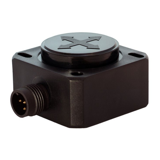
User Manual - QG40N Tilt/Acceleration Switch (SIL1 PLc) V2.0 3 Quick Reference • One housing type: 40x40mm plastic. • Two types of Tilt switch: 1-axis (vertical plane) up to ±170° range, outputs 2x NPN or 2xPNP 2-axis (horizontal plane) up to ±80° range, outputs 2x NPN or 2xPNP •... -
Page 6: Functional Description
User Manual - QG40N Tilt/Acceleration Switch (SIL1 PLc) V2.0 4 Functional Description Safety Switch Explained The safety function of the switch sensor is to generate the requested switching behaviour based on inclination or acceleration values (caused by gravitation) measured by a MEMS acceleration sensor chip. -
Page 7: Safety Level
User Manual - QG40N Tilt/Acceleration Switch (SIL1 PLc) V2.0 Safety Level SIL safety level: SIL CL1 (claim limit 1 according to IEC 62061) PL safety level: PLc (according to EN ISO 13849) Architecture: HFT=0 (according to IEC 62061) & CAT2 (according to EN ISO 13849) This is a self-certified safety device. -
Page 8: Mems Interrupt Error
The output of the sensor can be extra filtered by a 1 order low-pass filter. Default this output filter is disabled. Via the optional ‘QG40N configurator’ a -3dB frequency or RC-time can be configured. A longer low-pass filter time results is a smaller bandwidth and therefore a more stable output signal (less noise), but also more phase delay. -
Page 9: Output Explained
User Manual - QG40N Tilt/Acceleration Switch (SIL1 PLc) V2.0 Output Explained DIS Tilt/Acceleration switch has either PNP or NPN output, the connection of the load depends on the output type. Figure 1 - PNP output Figure 2 - NPN output In case the sensor is defect, or cable is broken, the sensor is in non-conducting mode, which is "critical". -
Page 10: Zero Adjustment
User Manual - QG40N Tilt/Acceleration Switch (SIL1 PLc) V2.0 Zero Adjustment To eliminate mechanical offsets, a zero adjustment can be performed during the 1 minute after power up the zeroing input is sensitive for a zeroing action. Sequence: 1. Left input unconnected during power up for at least 0.5s 2. -
Page 11: Switch Points
User Manual - QG40N Tilt/Acceleration Switch (SIL1 PLc) V2.0 4.7.1 Switch Points Switch points (±S) is a pair of pre-defined angles which set off the operation zone and critical zone (→4.5 Output explained). The S can be set with a unit of 0.1° and in default only symmetrical switch points are allowed, ie. -
Page 12: Delay Times
User Manual - QG40N Tilt/Acceleration Switch (SIL1 PLc) V2.0 Figure 6 - Hysteresis Example: Switch point = ±80°, hysteresis = 0.5° The sensor switches from conducting(operation) to non-conducting(critical) exactly at ±80°, but it switches from non-conducting(critical) back to conducting (operation) at ±79.5° (80° - 0.5°) instead. -
Page 13: Mounting
User Manual - QG40N Tilt/Acceleration Switch (SIL1 PLc) V2.0 Figure 7 - Mechanical drawing of QG40N with a male M12 Mounting Figure 8 - Horizontal mounting 2-axis Figure 9 Vertical mounting 1-axis • The sensor should be mounted on a stable flat surface with at least two screws tightened. -
Page 14: Connection
User Manual - QG40N Tilt/Acceleration Switch (SIL1 PLc) V2.0 Connection The sensor is equipped with Default: 5-pins M12 connector male (A-coding). See datasheets for details Optional: Cable with open ended wires. See datasheets for details Pin Assignment Pin 1 + Supply Voltage... -
Page 15: Abbreviations And Definitions
User Manual - QG40N Tilt/Acceleration Switch (SIL1 PLc) V2.0 6 Abbreviations and definitions SIL1 Safety Integrity Level 1 Performance Level d Hardware Fault Tolerance MTTFd Mean time to dangerous failure SRFRT Safety Related Fault Response Time CAT2 Category 2 μC...
Need help?
Do you have a question about the QG40N and is the answer not in the manual?
Questions and answers