Table of Contents
Advertisement
Quick Links
FT 200 - System
FT 200 CAP - System
Betriebsanleitung - Deutsch........................................................................ 2
Operating instructions - English................................................................ 41
Instructions d'utilisation - Français............................................................ 81
Manual de instrucciones - Español......................................................... 121
Istruzioni d'uso - Italiano ......................................................................... 160
Manual de instruções - Português .......................................................... 199
Advertisement
Table of Contents

Subscribe to Our Youtube Channel
Related Manuals for Häfele FT 200


Summary of Contents for Häfele FT 200
- Page 1 FT 200 - System FT 200 CAP - System Betriebsanleitung - Deutsch................ 2 Operating instructions - English..............41 Instructions d'utilisation - Français............81 Manual de instrucciones - Español............121 Istruzioni d'uso - Italiano ................. 160 Manual de instruções - Português ............199...
-
Page 2: Table Of Contents
8.2 Operation with user key with deadbolt lock function ............... 64 8.3 Programming permanent deadbolt lock operation ..............65 8.4 Allocating the user keys in keyed to differ operation (FT 200 + max. 1x MLA 8) ....66 8.4.1 Allocating user keys by means of consecutive lock allocation ..........66 8.4.2 User key allocation by unlocking the locks ................ - Page 3 10.2 FT 200 / FT 200 CAP as a switching device for the alarm ............ 71 10.3 One MLA 6P at the FT 200 / FT 200 CAP in keyed alike operation ........72 10.4 Several MLA 6P at the FT 200 / FT 200 CAP in keyed alike operation ......... 73 10.5 An MLA 8 on FT 200 / FT 200 CAP in keyed alike and/or keyed to differ...
-
Page 4: About This Document
1. About this document These operating instructions are valid for the “FT 200 / FT 200 CAP” system. They are part of the system and must be kept until the system is disposed of. 1.1 Target groups of the operating instructions The target groups of the operating instructions are: •... -
Page 5: Improper Use
2.2 Improper use Any use that is not mentioned in chapter 2.1 Proper use is considered improper. The following list outlines examples of improper use: • Outdoor use • Use in aggressive (containing salt or chlorine, for example) or damp environments •... -
Page 6: General Safety Instructions
2.4 General safety instructions The product has been built in accordance with the latest state of technology and the recognised technical safety regulations. Nevertheless, danger to persons or damage to the product or other property could occur during installation and use. ARNING Risk due to failures or faults in electromagnetically sensitive devices The electromagnetic radiation of the product can cause faults in sensitive parts –... -
Page 7: Structure And Function
• LED red/green Red: In operation, lock engaged Green: Lock disengaged Furniture terminal • System control unit FT 200 / FT 200 CAP • Connections for max. 4 furniture locks EFL 3 / EFL 3C Furniture lock • Electronically operated furniture lock... - Page 8 • Note: the order of the EFL 3 / EFL 3C connections always starts at the FT 200 / FT 200 CAP, so that if there are more than four EFL 3 / EFL 3C, the 5 will be connected to output 1 of the MLA 8.
- Page 9 Description CC 200 Powerbank • Connection cable for a Powerbank for the emergency power supply of the FT 200 in the event of a power failure (emergency opening) When using a Powerbank: • Disconnect the FT 200 from the mains. Parallel operation is not permitted! •...
-
Page 10: Technical Data
3.2 Technical data FT 200 / FT 200 CAP furniture terminal Feature Value Power supply 12 V DC, ± 20 % Current consumption max. 690 mA (incl. 4x EFL 3) Ambient temperature 0 - 55 °C Relative humidity 10 to 95%, not condensed... - Page 11 EFL 3 / EFL 3C furniture lock Feature Value Power supply 12 V DC Continuous current consumption ≤ 10 mA Current consumption max. 130 mA/40ms Operating temperature 0 - 50 °C Relative humidity 10 to 95%, not condensed Degree of protection IP20 Tensile load 1,000 N...
-
Page 12: Functions
In the event of a power failure, the locks retain the locking status which was present when the power failed. Keyed alike operation (= factory setting) An authorised user key simultaneously opens all locks connected to furniture terminal FT 200 / FT 200 CAP and, if applicable, multi-lock adapters MLA 6P / MLA 8. - Page 13 Keyed to differ operation An authorised user key simultaneously unlocks only certain locks, even though several are connected to the FT 200 / FT 200 CAP furniture terminal, and also the MLA 6P / MLA 8 multi- lock adapters if necessary.
-
Page 14: Factory Settings
3.4 Factory settings Parameter Value Open time (duration of unlocking period in latchbolt lock operation) 3 seconds • The open time can be set to up to 30 seconds at one second intervals in stand-alone operation 8.5 Adjusting the open time, page 69. •... -
Page 15: Installation References
EFL 3 / EFL 3C or for exchanging the FT 200 / FT 200 CAP. • Fix electrical cables in place once they have been laid in the furniture (e.g. -
Page 16: Commissioning
5. Commissioning The system is supplied in simple operation mode for stand-alone operation (SA). This document describes the commissioning process for stand-alone operation only. Start-up details for using the system with Dialock software applications can be found in the Dialock software documentation. The start-up process begins automatically once the power plug has been connected. -
Page 17: Commissioning App (Häfele My Dialock Manager)
5.1 Commissioning app (Häfele My Dialock Manager) The following functions are available with the Häfele My Dialock Manager app: Basic function: • Programming and commissioning of up to three terminals, • Programming of user keys (unlimited number), • Use of the door open alarm (duration 20 seconds, cannot be edited), Full range of functions (licence-dependent), •... - Page 18 Tag-it ™ISO Tag-it ™ISO Prerequisites: Programming key card Clearing key card 1. Plug in the power plug. 2. Hold the programming key card in front of the antenna during this 5-second period. Acoustic signal is heard. LED flashes green ...
-
Page 19: Programming User Keys
6. Programming user keys An authorised user key is needed to unlock a EFL 3 / EFL 3C lock. Locking authorisation must be allocated to this user key. The following user keys can be programmed: User key Locking authorisa- Functionality tion Normal user key Latchbolt lock... -
Page 20: Programming A Normal User Key
6.1 Programming a normal user key Tag-it ™ISO Prerequisites: Programming key card User keys 1. Hold the programming key card in front of the 2. Hold the user key in front of the antenna during antenna. this 5-second period. ... -
Page 21: Programming A Privileged User Key
6.2 Programming a privileged user key Tag-it ™ISO Prerequisites: Programming key card User keys 2x/s 1. Hold the programming key card in front of the 2. Hold the programming key card in front of the antenna. antenna again during this 5-second period. ... -
Page 22: Programming A User Key With Deadbolt Lock Function
6.3 Programming a user key with deadbolt lock function Tag-it ™ISO Prerequisites: Programming key card User keys 2x/s 1. Hold the programming key card in front of the 2. Hold the programming key card in front of the antenna. antenna again during this 5-second period. ... -
Page 23: Clearing Locking Authorisations
7. Clearing locking authorisations 7.1 Erasing the locking authorisation of an individual user key Tag-it ™ISO User key with locking Prerequisites: Clearing key card authorisation to be cleared 1. Hold the clearing key card in front of the 2. Hold the user key in front of the antenna during antenna. -
Page 24: Operation
8. Operation 8.1 Operation with a normal user key Normal user key with “latchbolt lock operation” locking authorisation Prerequisites: (self-locking action) 1. Hold the user key in front of the antenna. 2. Remove user key. Acoustic signal is heard. LED switches to LED illuminates green. -
Page 25: Operation With User Key With Deadbolt Lock Function
8.2 Operation with user key with deadbolt lock function Prerequisites: User key with deadbolt lock function (permanent open) A user key with the deadbolt lock function also has the “latchbolt lock operation” locking authorisation (self-locking action) 8.1 Operation with a normal user key, page 63 1. -
Page 26: Programming Permanent Deadbolt Lock Operation
Acoustic signal is heard. LED flashes in Acoustic signal is heard. LED continues to green for 5 seconds. flash in green and then goes to continuous red. The FT 200 / FT 200 CAP is now set to permanent deadbolt lock operation. -
Page 27: Allocating The User Keys In Keyed To Differ Operation (Ft 200 + Max. 1X Mla 8)
8.4 Allocating the user keys in keyed to differ operation (FT 200 + max. 1x MLA 8) 8.4.1 Allocating user keys by means of consecutive lock allocation Tag-it ™ISO Prerequisites: Programming key card User keys 1x/s 1. Hold the programming key card in front of the 2. - Page 28 5. Remove programming key card. 6. Hold all user keys which are to be given the locking authorisations for lock 2 in front of the The LED continues to flash in green 2x in antenna one after another. succession for approx. 15 seconds. ...
-
Page 29: User Key Allocation By Unlocking The Locks
8.4.2 User key allocation by unlocking the locks In keyed different operation, a maximum of one MLA 8 can be connected to the FT 200. Locks which are not to be allocated to the respective user key must be safeguarded against unintentional unlocking (e.g. -
Page 30: Adjusting The Open Time
( Macros, page 48). After a complete reset or setting the FT 200 / FT 200 CAP furniture terminal to “permanent deadbolt lock operation”, the set opening time is cleared and the factory setting of 3 sec or deadbolt lock operation are activated. -
Page 31: Extensions And Connections
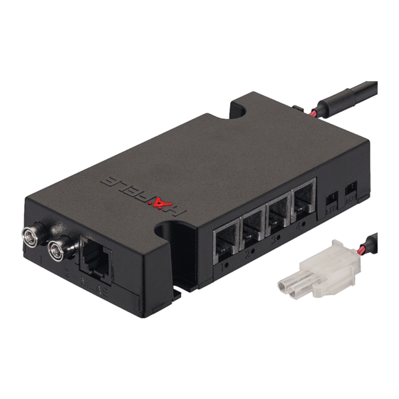
9. Extensions and connections The system can be extended. The following connections are available on the FT 200 / FT 200 CAP furniture terminal: Fig. 2: FT 200 / FT 200 CAP connections Connection Description Reset button • Reset 12. -
Page 32: Installation Examples
FT 200 / FT 200 CAP only activates the alarm if all EFL 3 / EFL 3C are locked. ON OFF FT 200 Vout FT 200 CAP Input Input Fig. 5: Installation example 2 - FT 200 / FT 200 CAP as a switching device for the alarm [1]... -
Page 33: One Mla 6P At The Ft 200 / Ft 200 Cap In Keyed Alike Operation
Contacto del supervision, ext. Contato de monitoramento, ext. max. 10 m max. 10 m max. 10 m max. 10 m Fig. 6: Installation example 3 - One MLA 6P at the FT 200 / FT 200 CAP in keyed alike operation. -
Page 34: Several Mla 6P At The Ft 200 / Ft 200 Cap In Keyed Alike Operation
PS 4 (max. 2,5 A) Fig. 7: Installation example 4 - Several MLA 6P at the FT 200 / FT 200 CAP in keyed alike operation. The voltage supply of multi-lock adapter MLA 6P can be provided directly via power supply unit PS 4 or (max. -
Page 35: Operation
5 m Fig. 8: Installation example 5 - One MLA 8 at the FT 200 / FT 200 CAP in keyed alike and/or keyed to differ operation. In keyed different operation, a maximum of one MLA 8 can be connected to the... -
Page 36: Several Mla 8 At The Ft 200 / Ft 200 Cap In Keyed Alike Operation
PS 4 (max. 2,5 A) Fig. 9: Installation example 6 - Several MLA 8 at the FT 200 / FT 200 CAP in keyed alike operation. The voltage supply can be provided directly via the PS 4 power supply or (max. 1x) from MLA 8 to MLA 8 . -
Page 37: Troubleshooting
11. Troubleshooting Fault when opening Possible cause Remedy Acoustic signal is heard • User key is not authorised. • Program the user key. twice. 6. Programming user keys, page 58 LED for the FAN 200 • Distance between user key •... -
Page 38: Simple Reset
12.1 Simple reset A simple reset is required in the following cases: • Loss of programming and erasing key (master keys). After a simple reset, the allocated master keys are cleared and reallocation is required (LED continuously flashing in green). Continued use of the terminal is not possible until a restart with new master keys ... -
Page 39: Complete Reset
The LED flashes rapidly in green and red. All data and access rights are cleared. The FT 200 switches to start-up mode 5. Commissioning, page 55) 13. Cleaning and maintenance 13.1 Cleaning • Only clean visible antenna surfaces as required. -
Page 40: Maintenance
Please note the country-specific regulations. 16. EU Declaration of conformity Sphinx Electronics GmbH & Co KG hereby declares that the FT 200 / FT 200 CAP furniture terminal in connection with the EFL 3 / EFL 3C furniture lock, FAN 200 antenna, the PS 4 power supply unit and MLA 8 multi-lock adapter are compliant with directives 2014/53/EU and 2011/65/EU. -
Page 41: Approval According To Part 15 Of The Fcc Rules
18. Approval according to Part 15 of the FCC rules NOTE: This equipment has been tested and found to comply with the limits for a Class B digital device, pursuant to Part 15 of the FCC Rules. These limits are designed to provide reasonable protection against harmful interference in a residential installation.
Need help?
Do you have a question about the FT 200 and is the answer not in the manual?
Questions and answers