Table of Contents
Advertisement
Quick Links
Advertisement
Table of Contents

Subscribe to Our Youtube Channel
Summary of Contents for Unimig RAZOR CUT 45
- Page 1 CUT 45 U14007 | Operating Manual...
-
Page 2: Table Of Contents
RAZOR CUT 45 AIR COMPRESSOR OPERATING MANUAL 1. Safety 2. Package Contents 3. Compressor Specifications 4. Compressor Layout 4.1 Front Panel Layout 4.2 Rear Panel Layout 4.3 Air Regulator Layout 5. Machine Setup 6. Filter Replacement... -
Page 3: Safety
RAZOR CUT 45 AIR COMPRESSOR OPERATING MANUAL 1. Safety Welding and cutting equipment can be dangerous to both the operator and people in or near the surrounding working area if the equipment is not correctly operated. Equipment must only be used under the strict and comprehensive observance of all relevant safety regulations. - Page 4 RAZOR CUT 45 AIR COMPRESSOR OPERATING MANUAL Fire hazard • Welding/cutting on closed containers, such as tanks, drums, or pipes, can cause them to explode. Flying sparks from the welding/cutting arc, hot workpiece, and hot equipment can cause fires and burns. Accidental contact of the electrode to metal objects can cause sparks, explosion, overheating, or fire.
- Page 5 RAZOR CUT 45 AIR COMPRESSOR OPERATING MANUAL Caution Working environment • The environment in which this welding/cutting equipment is installed must be free of grinding dust, corrosive chemicals, flammable gas or materials etc., and at no more than a maximum of 80% humidity.
-
Page 6: Package Contents
RAZOR CUT 45 AIR COMPRESSOR OPERATING MANUAL 2. Package Contents RAZOR CUT 45 Air Compressor Air Hose Mounting Brackets & Screws... -
Page 7: Compressor Specifications
RAZOR CUT 45 AIR COMPRESSOR OPERATING MANUAL 3. Compressor Specifications Technical Data Parameter Values U14007 Input Amperage 3.7 ±5% Rated Power 780 Watts ±5% Rated Air Pressure (MPa) 0.25±0.05 Maximum Instantaneous Working Pressure (MPa) Dimensions (mm) 463×187×236 Weight (kg) 17.15 Protection Class... -
Page 8: Compressor Layout
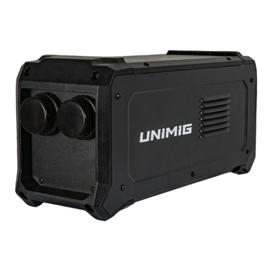
RAZOR CUT 45 AIR COMPRESSOR OPERATING MANUAL 4. Compressor Layout 4.1 Front Panel Layout 4.2 Rear Panel Layout 1. Intlet Air Filter Covers 2. Air Outlet 3. Compressor Operation Indicator 4. Power Input Cable (for RAZOR CUT 45) -
Page 9: Machine Setup
*ENSURE YOUR MACHINE IS OFF AND UNPLUGGED BEFORE STARTING ASSEMBLY PROCESS* 1. Start by installing the brackets to the bottom of the RAZOR CUT 45. Using a philips screw driver, loosely tighten 2 screws on each backet into the open holes on the base of the CUT 45. -
Page 10: Filter Replacement
Simply press the plug in until you hear a click. CUT 45. 6. You are now ready to plug your RAZOR CUT 45 in and use it. The compressor will automatically kick on when more air flow is needed. 6. Filter Replacement The RAZOR CUT 45 Air Compressor has two air filters located at the front of the machine. - Page 11 Ensure the inlet holes are pointed in a downward angle. Replacement Internal Filters These are factory replacement filters for your RAZOR CUT 45 Air Compressor. The filters are sold in packets of 2. SKU: U14010 Add-on Air Filter The UNIMIG Plasma Cutter Air Filter eliminates contaminants such as sputter caused by moisture and oil from compressed air lines.
- Page 12 PH: (02) 9780 4200 PH: (07) 3333 2855 PH: (03) 8682 9911 PH: (08) 6363 5111 FAX: (02) 9780 4210 FAX: (07) 3274 5829 FAX: (03) 9333 7867 FAX: (08) 9417 4781 EMAIL: sales@unimig.com.au EMAIL: qld@unimig.com.au EMAIL: sales@unimig.com.au EMAIL: wasales@unimig.com.au...
Need help?
Do you have a question about the RAZOR CUT 45 and is the answer not in the manual?
Questions and answers