Table of Contents
Advertisement
Quick Links
Advertisement
Table of Contents

Summary of Contents for HANSA-FLEX HK S TKV
- Page 1 USER MANUAL HK S TKV Analogue Power Meter Stainless steel design Pressures up to 350 bar Volume flow up to 190 l/min Temperature display up to 120°C Internal overpressure protection Can be used with all mineral oils ...
-
Page 2: Table Of Contents
TABLE OF CONTENTS INTRODUCTION UNPACKING AND CHECKING THE PRODUCT FUNCTIONAL PRINCIPLE INSTALLATION Important information Installing the volume flow meter Installing the power meter OPERATION Information about the power meter CONDUCTING THE POWER MEASUREMENT General information Standard test condition Pump test Test sequence Pressure relief valve test Test sequence... -
Page 3: Introduction
INTRODUCTION This volume flow meter is a robust industrial-grade inline gear flow meter that is available in an aluminium, brass or stainless steel design for the purpose of monitoring many different fluids. Available in seven connection sizes from 1/4... 3 inches for flow ranges from (0.02...0.20 gal/min) 0.1...0.75 l/min to (20...300 gal/min) 100...1100 l/min. -
Page 4: Unpacking And Checking The Product
UNPACKING AND CHECKING THE PRODUCT Perform the following steps once you receive the product: If the product packaging is damaged, ask the shipping agent to be present when the product is unpacked. If the product is damaged and the shipping agent is not present, ask for an inspection by the representative of the shipping agent within 48 hours of delivery and lodge a complaint with the shipping agent. -
Page 5: Functional Principle
FUNCTIONAL PRINCIPLE The volume flow meter is a float-type measuring device. A sharp-edged baffle (1) located in the piston assembly (2) forms an annular opening with the contoured measuring cone (3). The piston assembly features a cylindrical PPS/ceramic magnet (4) that is coupled magnetically to an external display magnet (5) which moves in direct response to the movement of the piston. -
Page 6: Installation
INSTALLATION Important information CAUTION! This product should be installed and maintained by technically qualified personnel who have been trained on this specific product. CAUTION! Read through the instructions before you install the device. If you have any questions about installation or maintenance, call your local supplier to obtain further information. - Page 7 The volume flow meter is a device that is easy to install. However, the following measures are recommended to ensure it can be operated safely and without any faults: Align the pipeline precisely. The piping should be aligned precisely and be of the ...
-
Page 8: Installing The Volume Flow Meter
Unidirectional devices (such as this volume flow meter) must not be operated in the direction opposite to the one shown by the flow arrow. The piston acts like a non- return valve and blocks the flow in the opposite direction. This causes an excessive difference in pressure that may damage the internal components. - Page 9 2. Choose an installation location that is suitable for inspection and product maintenance. To connect the volume flow meter to the pipeline system, place a flat spanner on the wrench flats of the volume flow meter next to the pipe connection that is to be installed. Do not screw on the opposite end of the volume flow meter as this may cause leaks.
-
Page 10: Installing The Power Meter
Installing the power meter 1. Mount the power meter so that the fluid flows in the direction of the flow arrow. ( See Figure 1. Page 7 2. Install the power meter at any point in the hydraulic circuit, so that the volume flow, pressure and temperature displays can be read easily. - Page 11 Figure 5: Power meter in the transport case 4. Turn the premounted volume flow meter by hand after installation so that you can see the flow scale. Turn the volume flow meter by hand so Never use a flat spanner to turn the that you can see the display scale.
-
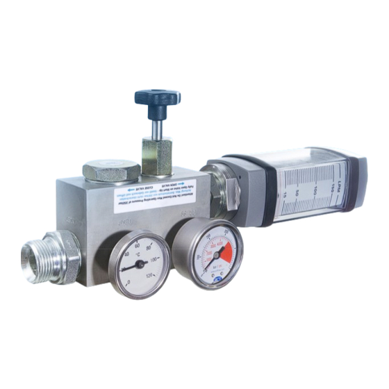
Page 12: Operation
Open the load valve (free flow) Close the load valve Pressure loading unit Figure 7: Stainless steel power meter, 350 bar Type: HK S TKV Stainless steel Loading valve (load valve) Volume flow meter Thermometer Pressure gauge... -
Page 13: Conducting The Power Measurement
CONDUCTING THE POWER MEASUREMENT CAUTION! The information in this user manual is intended for general application only. All the information that is provided by the manufacturer and/or constructor of the hydraulic components of the machine, the hydraulic system, should be followed. Special systems may require special test procedures. -
Page 14: Pump Test
Pump test System pressure System PRV gauge Tank Figure 8: Schematic diagram of pump test Figure 9: Hydraulic diagram of pump test Test sequence 1. The power meter (4) is connected on the input side (IN) to the pressure line of the pump (1), which is preferably safeguarded by means of a pressure relief valve (3). -
Page 15: Pressure Relief Valve Test
4. The volume flow Q of the pump is now displayed as a function of the load pressure (4.1) on the scale of the volume flow meter (4.4) in [l/min] (LPM). 5. The values that are read on the power meter (pressure, volume flow, temperature) can then (pump specification) be compared with the p/Q characteristic curve in the data sheet from... -
Page 16: Test Sequence
Test sequence 1. The power meter (4) is connected on the input side (IN) to the pressure line of the pump (1), which is safeguarded by means of a pressure relief valve (PRV) (3). 2. With a fully opened loading valve (4.3), the hydraulic oil is returned to the tank on the output side (OUT). -
Page 17: Maintenance
MAINTENANCE WARNING! Before you remove the power meter from the line, check that the hydraulic system has been depressurised. Failure to follow this instruction may cause serious physical injuries or death and/or material damage. Pressure release Before starting work: mobile hydraulic systems must be depressurised, ... -
Page 18: Removing The Dust Protection Casing
pressure loading unit 3. Disconnect the volume flow meter (2) from the “ “, see Figure 7 page 11) (see Table 1, page 4 4. Remove the end caps (13) ) from the volume flow meter and note down the order in which you dismantle things as a reference for when you reassemble them later 5. -
Page 19: Reconnecting The Magnetic Coupling
Reconnecting the magnetic coupling This piston-type volume flow meter is less sensitive to impacts and vibrations than other float- type designs. The magnetic coupling dispenses with the need for a mechanical connection, which may become worn or loose over the lifespan of the measuring device. However, a pressure spike or sudden increase in volume flow may cause the piston magnet to (see move at such a high velocity that the piston magnet (4) and the external display ring (5) - Page 20 The burst pressure protection breaks at a pressure of over 400 bar. Stainless steel volume flow meters are designed for an operating pressure of up to 350 bar and a safety factor of 3:1. K-MEP2470 Burst pressure protection HANSA-FLEX article number: Figure 11: Power meter with burst pressure protection Figure 12: Locking screw Figure 13: (Hex nut) screw-in part with safety disc 1.
-
Page 21: Technical Data
TECHNICAL DATA Temperature range Standard: -20°C to +116°C Nominal pressure (safety factor 3:1) Please note: Pressure 10 PSI ~ 0.69 BAR Aluminium models (3500 psi) ~ 250 bar max. Stainless steel models, sizes ¼“ and ½“ (6000 psi) ~ 420 bar max. ... -
Page 22: Accuracy
Accuracy +/- 2% on the full scale Repeatability +/- 1% Thread BSPP ISO1179 Pressure display Pressure gauge with glycerine filling, connection on rear (NPT 1/8“) Stainless steel model (0 - 6000 psi) 0 - 400 bar Temperature display Insertion thermometer without glycerine filling Stainless steel model 0-120°C Loading valve Size ¾“... -
Page 23: Dimensions
DIMENSIONS Page 22 Valid from: 15.02.2021 / Source: VAM-UM-00551-EN-04 Despite careful checking, we cannot exclude the possibility of errors in this document and we accept no liability for the information it contains.
Need help?
Do you have a question about the HK S TKV and is the answer not in the manual?
Questions and answers