Table of Contents
Advertisement
Advertisement
Table of Contents

Related Manuals for PIKO SmartControl WLAN


Summary of Contents for PIKO SmartControl WLAN
- Page 1 PIKO SmartControl – wlan the future of digital control! OWNER'S MANUAL...
- Page 2 ® ® PIKO reserves the right to make technical and/or color changes to this product. Errors and omissions are possible and delivery dates are not guaranteed. Dimensions and illustrations are subject to change. Duplication and/or reproduction of this document in any form without written permission of PIKO is prohibited.
-
Page 3: Table Of Contents
3.7.2 CV Programming on the Main track (POM) ................ 31 3.7.3 CV Programming on the Main track (XPOM) ............. 32 for experts 3.7.4 Update menu for PIKO SmartDecoder XP 5.1 and further versions (PSD) ..... 33 3.8. The Settings menu [ ] ....................34 3.8.1 Set language ......................... - Page 4 - System response to a lost connection ................. 47 3.8.9 Verschließen einzelner Controllermenüs (Kindersicherung) ........... 48 RailCom Plus ........................49 ® Technical data ........................50 a. PIKO SmartBox ......................50 wlan b. PIKO SmartController ....................50 wlan EU- Declaration of Conformity / FCC Notice ..............50 Product safety warning .......................
-
Page 5: System Properties
Programming on the wlan Main (POM and XPOM). • PIKO SmartDecoders from version XP 5.1 and upwards can be updated with the SmartControl. • All PIKO SmartControl components can be updated. wlan •... -
Page 6: Connections
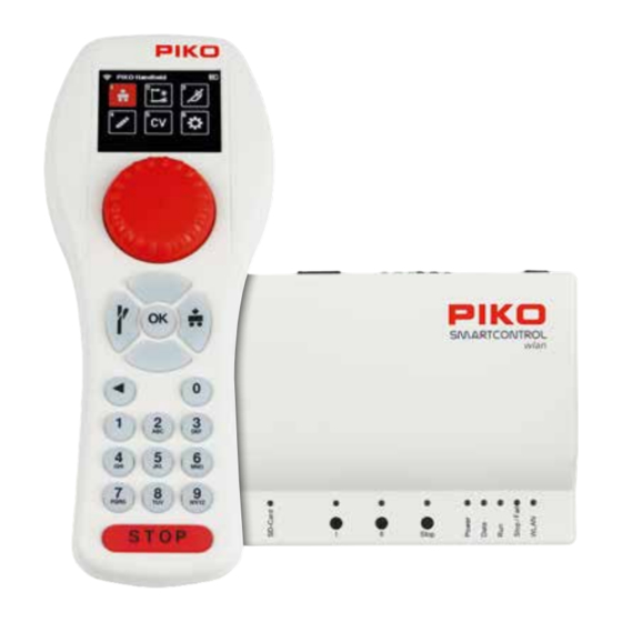
The PIKO SmartBox has ports for a main track, a programming track, a PIKO SmartBooster, the wlan PIKO SmartTester, as well as USB-C port and a socket for the power cord. Connection points on the PIKO SmartBox wlan Back side... - Page 7 Controls and display elements of the PIKO SmartBox wlan Buttons Open use button (you can program this button for any function you want) WLAN "Fast Connect" (adjustable ) Stop: Track power On/Off switch A long press on start-up resets the SmartBox to factory settings...
-
Page 8: Putting The Piko Smartcontrol
"STOP" button for approx. 3 seconds to turn the throttle on again. After the PIKO start screen, the locomotive selection menu will appear on the display and the "STOP" button will flash (track voltage is turned off). -
Page 9: The Controls Of The Piko Smartcontroller
The devices are now paired when the two LEDs on the control panel stop flashing and the active WLAN symbol appears on the throttle. More information on "FastConnect" can be found in Chap. 3.8.5 "Select WLAN". 2. The controls of the PIKO SmartController wlan Overview of the controls... -
Page 10: Operating Of The Piko Smartcontroller
Adjustable for AC drive controller mode (factory setting) and DC drive controller mode (chap. 3.8.3). Buttons All train control and layout operation can be carried out comfortably using the backlit keyboard of the PIKO SmartControllerwlan. The durable keys have a clearly perceptible pressure point and are nearly wear-free. USB-C port... -
Page 11: The Main Menu
The previous locomotive will continue to run at the speed you left it at until you select it again and change its speed. The locomotive menu is factory set to locomotive address 3. To begin operating a locomotive with the PIKO SmartController , you wlan first call it up from the locomotive selection list by pressing the number key that matches the locomotive’s address (found in the top left of the field). - Page 12 System wlan After the desired locomotive has been called up, it can be run directly using the throttle’s dial. The dial will automatically turn to the speed the locomotive was traveling at when overtaken from the previous throttle. The display will now show the locomotive image stored in the locomotive editor, the current speed step, and the direction arrow including the speed bar underneath it on the lower left.
-
Page 13: The Accessory Menu [ ]
When the dial is turned back to the left, the speed of the locomotive is reduced until it stops. Another left turn will cause the locomotive to move in the opposite direction of travel. DC throttle mode is activated in the settings menu of the PIKO SmartController (chap. 3.8.3). -
Page 14: The Route Menu [ ]
System wlan Switching accessory addresses directly (without programming them) The accessories menu allows you to switch an accessory that has not yet been programmed into the SmartControl system. This is convenient for testing some accessory decoders or for testing out a train routing. -
Page 15: The Edit Menu [ ]
wlan 3.6. The Editor menu [ The SmartControl’s Editor menu allows you to edit data for locomotives, accessories, and routes. To begin editing, you must first select the editor menu icon. After selecting the editor menu, a locomotive icon, an accessories icon, and a route icon will appear on the display. - Page 16 OK button. If not, scroll down to the next highlighted frame To select the image for the BR 83.10, we scroll to the “PIKO” option and select it, as all PIKO locomotive images are available under the PIKO option.
- Page 17 wlan To set the number of DCC speed steps, move to the speed step display under the speed bar using the "down button". This is now highlighted in blue. Press the OK button to open the selection field for DCC speed steps. Now use the "down"...
- Page 18 System wlan By pressing the OK button, the two navigation arrows next to the function key field turn blue and the functions to be changed can now be selected via the keypad. If functions other than those shown are to be changed, you can use the "up" or "down"...
-
Page 19: Edit Accessories
wlan ... to save the new locomotive data set with the "Save" icon. At this point you can also delete this locomotive data record by using the "Recycle bin" icon. The display then reverts to the locomotive editor icon of the editor menu. By pressing the "back button"... - Page 20 System wlan Various steps can now be selected in this view. The first step is to enter the name and a brief description of the item. To do this, select the "Name" field and confirm it with the OK button The name will appear later in the accessories menu as an identifier for selecting the accessory and the description will appear when the desired item has been called up.
- Page 21 wlan The "Simple" entry is certainly the most common type and also the factory default setting. The desired decoder type is selected with the "up" or "down" button and confirmed with the OK button. The corresponding field is then highlighted in green. The top, still grey entry "RailCom Decoder"...
- Page 22 System wlan The switching direction (here green) can now be selected via the OK button. The respective setting is shown in color in the corresponding field. Once the first direction has been set, you must now use the "left" button to jump to the turnout symbol.
- Page 23 wlan There is no need to enter the type, since the factory setting "Simple" is used automatically here. Enter the first address for the red/green toggle, followed by the se- cond address to toggle yellow on/off. Then enter the activation time in 100ms steps.
-
Page 24: Edit Route
System wlan 3.6.3 Edit Route To create train routes, the route symbol is highlighted in the editor menu by using key 3 on the keypad or using the navigation keys followed by the OK button. A sequence of circuits of the edited accessories , pause times, previously edited routes, and so-called sub-routes can be added to a route. - Page 25 wlan In the following view we can now decide which type of route command should be entered as the first step. There are “accessory circuits”, “pauses” and previously edited “routes” (sub-routes) to choose from. The selection can be made using the navigation keys or using the number shown in each field.
- Page 26 System wlan The first step of our route now appears in the command sequence. In the second step, light signal LS12 needs to be added. To do this, we select the second field with key 2 on the keypad ..
- Page 27 wlan The second step in our sequence requires a five second pause to be inserted. To do this, we select the third field with key 3 ..and in the next window we activate symbol 2 for the pause. In the subsequent window, you can jump to the delay field and select it with the OK button.
- Page 28 System wlan In the selection, we select light signal LS12 using key 6 on the keypad or by using the navigation keys followed by the OK button. Now we can decide which signal aspect to switch. The signal should be set to "red"...
-
Page 29: Cv Programming Menu [ ]
3. A Programming track (PROG) is the traditional programming method where the locomotive is placed on an isolated track dedicated just to decoder programming. The fourth menu (PSD) is intended for updating PIKO SmartDecoder from version XP 5.1 and upwards. 3.7.1 CV programming on the programming track (PROG) Since programming on a programming track is the most common, it will be explained first. - Page 30 System wlan The panel's green Run LED will flash and a red "P" will appear in the top line of the next display window. Use the navigation keys to jump to the "CV" field and enter the CV number to be read or written. To do this, first press the OK button. The input field will now become solid.
-
Page 31: Cv Programming On The Main Track (Pom)
wlan 3.7.2 CV Programming on the Main track (POM) A prerequisite for main track programming is that the decoder address of the locomotive to be program- med is known. In addition to be programmable on the main track, CVs can also be read from the main track provided the decoder is capable of it. -
Page 32: Cv Programming On The Main Track (Xpom) For Experts
3.7.3 CV Programming on the Main track (XPOM) for Experts The PIKO SmartControl offers a relatively new type of programming method known as Program- wlan ming on the Main for Experts (XPOM). This is used to speed up access to CVs and to address the area of the CV banks that can only be accessed via CVs 31 and 32. -
Page 33: Update Menu For Piko Smartdecoder Xp 5.1 And Further Versions (Psd)
This menu can be used to update PIKO SmartDecoders beginning with version XP 5.1. The latest firm- ware can be found in the web shop on the PIKO website and can be copied to the SD card. To update a decoder it has to be in a locomotive... -
Page 34: The Settings Menu
System wlan 3.8. The Settings menu [ To assign settings in the PIKO SmartControl devices, the " " icon for wlan the settings menu must called up in the main menu by using key 6 or by the navigation keys followed by pressing the OK button. -
Page 35: Setting The Dial Settings
wlan The following window contains the setting options for the display (left) and for the keyboard backlighting (right). Using the “right” and “left” navigation keys you can switch between the two options. The value in the active field can be adjusted by turning the dial or using the "up"... -
Page 36: Smartcontroller Sleep Mode
System wlan 3.8.4 SmartController sleep mode If the throttle has not been used for some time during an operating session, it makes sense to go into sleep mode or shut down to conserve battery power. The time period between last use and activation of sleep mode or shutdown is adjustable. - Page 37 wlan Initially, the "Search" field will display on-screen. After confirmation with the OK button, the next window will ask if the throttle should connect directly with the command station via "FastConnect" or whether it should connect from a list of available Wi-Fi devices. Here you can choose between "FastConnect"...
-
Page 38: General Settings (Smartcontroller)
System wlan The selected Wi-Fi device now appears in the display. If you want to change the name of this Wi-Fi device, press the "down key" and the activated field will change from "Search" to the Wi-Fi symbol. Confirm this with the OK button. The name field is now solid red and the new name can be entered using the "telephone keypad". - Page 39 wlan In this field, the Controller name can be changed as you wish. To do this, activate the Name field with the OK button. Then enter the new name using the “telephone keypad”. Once the name has been entered and confirmed with the OK button, save the new name in the Controller via the "Save"...
-
Page 40: The Information Menu
System wlan The Controller can be reset to factory settings by highlighting the last field in the settings menu. To do this you will have to use the PIN you created in the previous step. The following Controller settings are then reset to factory settings: the Wi-Fi password, the Controller name, the throttle mode, sleep mode/shutdown settings, screen/keyboard brightness, and your PIN. - Page 41 “Station Mode”, provided your system has an internet connection. You can also download firmware updates to a PC by going to the PIKO Webshop and saving them on the SD card and then inserting the SD card into the SmartBox.
-
Page 42: Settings Menu Of The Smartbox (Command Station)
The updates will be saved to the SD card and displayed in the "Firmware" menu, where they can be installed. The serial numbers: This submenu shows the serial numbers of the PIKO SmartBox (55825B) and the PIKO SmartController wlan wlan (55823). This information is useful for service purposes. -
Page 43: Track Setting
wlan The submenu contains settings for the Main track connection port, assign- ment options for the three SmartBox buttons, SD card settings, and in the case of a StartSet SmartBox, the option to enter an activation code to upgrade to the full version. The track settings: This submenu lets you set the maximum output current to the main track. -
Page 44: Sd Card Settings
System wlan You can choose between three functions for buttons I and II. 1. Main track on (send power to the main track) 2. FastConnect (quick connection with a SmartController) 3. No function The Stop button has two options: 1. Power off (power to the main track must be switched on again using another button or a Controller) 2. -
Page 45: The Activation Code Inputs
“Start-Set”. This SmartBox can be upgraded to a full-fledged version via a paid upgrade. This upgrade can be purchased from PIKO dealers or the PIKO web shop. An activation code will be generated after the purchase that is entered into the fields of this menu using the “telephone keypad”... - Page 46 System wlan In order to set up the system’s self-contained Wi-Fi network, the "Ac- cessPoint mode" needs be activated. This is the factory default setting. The necessary settings can be entered in the next submenu, which can be selec- ted by highlighting it followed by pressing the OK button. By highlighting the "AccessPoint-Mode"...
-
Page 47: System Response To A Lost Connection
wlan In the following window, the required entries can be made using the same procedure as "AccessPoint mode", where the name of the desired Wi-Fi network and its password must be entered here. If these settings were saved using the "Save" icon and the SmartBox was then restarted, it is now integrated into the Wi-Fi network. -
Page 48: Verschließen Einzelner Controllermenüs (Kindersicherung)
System wlan 3.8.9 Limiting access to individual controller menus (child safety lock) To secure individual areas of the Controller from unauthorized access, these areas can be locked in such a way that they can only be accessed by entering a four-digit PIN. To do this, press key 9 on the keypad while in the settings menu, or navigate to this field and activate the menu with the OK button. -
Page 49: Railcom Plus
® in chapter 3.8.8. NOTE: If a PIKO SmartDecoder 4.1 (firmware version, with CV7 set between 28 and 35) was entered into this command station and was deleted again, you will need to reset the decoder by programming CV8 to a value of 1. -
Page 50: Technical Data
• Dimensions: 189 x 79 x 37mm - 7.4” x 3.1” x 1.5” inches EU Declaration of Conformity PIKO Spielwaren GmbH hereby declares that this product complies with Directive 2014/53/EU. The full text of the EU declaration of conformity is available at the following internet address: https:// www.piko.de/konformant... -
Page 51: Product Safety Warning
7. FAQs At this point we would like to refer you to the FAQ page on our website. You can find it in the PIKO web shop at www.piko-shop.de/?a=faq. There you will find the latest information on using the PIKO Smart- Controller system as well as detailed video tutorials. - Page 52 PIKO model trains – for every layout! PIKO Spielwaren GmbH Lutherstr. 30 96515 Sonneberg, GERMANY www.piko.de · hotline@piko.de...
Need help?
Do you have a question about the SmartControl WLAN and is the answer not in the manual?
Questions and answers
как подключить новый локомотив от пико
To connect a new PIKO locomotive with SmartControl WLAN:
1. Turn on the SmartControl WLAN system – Ensure the controller is powered on and the active WLAN symbol appears.
2. Rerail the locomotive – Place the PIKO locomotive on the track.
3. Activate track voltage – Press the "STOP" button to switch on the track voltage.
4. Automatic registration (if applicable) – If the locomotive supports RailCom Plus®, it will register automatically in the system.
5. Manual addition (if needed) – If the locomotive does not appear in the selection menu, navigate to the edit menu and add it manually to the locomotive database.
6. Select the locomotive – Use the locomotive selection menu to choose the newly added or automatically registered locomotive.
7. Start operation – Once selected, you can control the locomotive via the SmartControl WLAN system.
This process ensures the locomotive is properly connected and ready for operation.
This answer is automatically generated