
Summary of Contents for Shadin Digiflo-L
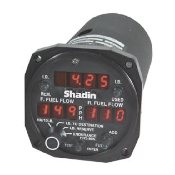
- Page 1 Digiflo-L ™ Digital Fuel Management System RS-232 and RS-422 output format with interface to LORAN-C and GPS receivers OPERATING MANUAL Single and Twin Engine Indicators For P/N: 91053XP Shadin Co., Inc.
-
Page 2: Table Of Contents
TABLE OF CONTENTS 1. GENERAL DESCRIPTION .............3 1.1 THE SYSTEM PROVIDES ..................4 1.1.1 SPECIFIC RANGE................. 4 1.1.2 FUEL TO DESTINATION..............4 1.1.3 FUEL RESERVE ..................4 1.1.4 ENDURANCE..................4 1.1.5 FUEL FLOW ................... 5 1.1.6 FUEL USED .................... 5 1.1.7 FUEL REMAINING ................ - Page 3 3.1.6 FUEL TO DESTINATION..............13 3.1.7 FUEL RESERVE .................. 14 3.2 WARNINGS ......................15 3.2.1 NOT ENOUGH FUEL................. 15 3.2.2 RESERVE FUEL WILL BE USED ..........15 3.2.3 LOW ENDURANCE ................15 3.2.4 LOW FUEL REMAINING..............15 4. EMERGENCY PROCEDURES........... 16 5.
-
Page 4: General Description
Digiflo-L is set up to measure the flow of fuel in either gallons, liters, or pounds, and it can be installed on virtually any reciprocating or turbine engine by selecting the proper size fuel... -
Page 5: The System Provides
Fuel Reserve = Fuel Remaining – Fuel to Reach Destination. 1.1.4 ENDURANCE Digiflo-L calculates the time left to fly in hours and minutes based on the fuel remaining and the present fuel flow. -
Page 6: Fuel Flow
1.1.5 FUEL FLOW The system provides a digital readout of the fuel per hour to a tenth of a gallon up to 100 gallons and to the nearest gallon above 100 gallons. For the pounds version, the readout is to the nearest pound up to 999 lbs./hour and to the nearest 10 lbs. -
Page 7: System Components
SYSTEM COMPONENTS The system consists of three (3) basic units: the fuel flow transducer, the navigation receiver (Loran-C or GPS) and the panel mounted unit. 1.2.1 FUEL FLOW TRANSDUCER The fuel flow transducer mounted in the fuel line measures the flow of fuel and generates electrical pulses directly proportional to the fuel flow. -
Page 8: Test Function
TEST FUNCTION Diagnostic software is built into the system. To activate it, press the TEST/ENTER button and hold until “8’s” begin to appear across the display windows and then release. If the test is successful, the word “Good” will appear on the upper display window for three seconds. -
Page 9: Preflight Procedures
2. PREFLIGHT PROCEDURES Digiflo-L is a fuel flow measuring system and NOT a quantity- sensing device. A visual inspection and positive determination of the usable fuel in the fuel tanks is a necessity. Therefore, it is imperative that the determined available usable fuel be manually entered into the system. -
Page 10: Preflight Check
After reaching the correct total usable fuel figure, press the TEST/ENTER button and the computer will store that number as full fuel. The word “FUL” disappears and the computer will return to the operating mode. Release the FULL/ADD toggle switch. To verify that the data is stored properly, press the TEST/ENTER button. -
Page 11: Fuel Added
check the Data Interface Integrity (not available without signal). If the system is not capable of reading the navigational receiver data, the word “LbAd” will be displayed on the upper window. If the Loran-C or GPS receiver is turned off, the display shows “LoFF”. -
Page 12: Partial Fuel Added
• Release the REM button and the TEST/ENTER button to enter the total usable fuel on board into memory. • If the required figure is exceeded, follow the procedure in this manual, section 2.6 Correcting Fuel on Board Entry Error. FULL/ADD Toggle Switch Method •... -
Page 13: Correcting Fuel On Board Entry Error
• Release the FULL/ADD toggle switch so it returns to the center position. The computer will add the added fuel remaining and use the total as the current fuel remaining. • To verify, press the REM button. The current usable fuel remaining will be displayed on the upper window. -
Page 14: Inflight Operations
3. INFLIGHT OPERATIONS INSTRUMENT OPERATION 3.1.1 FUEL FLOW Fuel Flow is displayed continuously on the lower display windows. 3.1.2 FUEL USED Fuel used is displayed by pressing the USED button. The information is shown on the upper display window as long as the button is held in the USED position. -
Page 15: Fuel Reserve
total distance record is provided in the serial message.) This assumes the aircraft ground speed and fuel flow remains constant and the aircraft remains on flight plan course. (Readings obtained during climb and descent are invalid.) 3.1.7 FUEL RESERVE Fuel reserve is selected by rotating the rotary switch to the FUEL RESERVE position. -
Page 16: Warnings
3.2.3 LOW ENDURANCE The Digiflo-L can be configured to display a warning based on the time remaining to fly. When the rotary switch is in the ENDURANCE position, and the actual endurance is less than the pre-programmed Endurance Warning Time, the data in the right half of the display flashes. -
Page 17: Emergency Procedures
4. EMERGENCY PROCEDURES In case of electrical power failure in- flight, the instrument will cease to function. After restoring power, the system will resume accurate fuel flow reading, but time remaining, fuel used, fuel remaining, fuel reserve, fuel to destination and all warnings will not be accurate unless the duration of power failure is known and fuel consumption during the electric power failure is calculated and subtracted from fuel remaining. -
Page 18: Configuration Data Entry
Previously, all settings depended upon the switches mounted on the processor board. Currently, the Digiflo-L processor board and software version 60.10.XX has a feature that is referred to as Manual Entry Mode. In this mode, the Flow Meter settings are stored as two groups: Group 1 and Group 2. - Page 19 Locations of the switches for the Digiflo-L are as follows: Display Side Each switch has 16 positions, 0-9, A, B, C, D, E, and F. Note: A hole has been cut into the can to allow access to switches normally covered by the red K- factor sticker.
- Page 20 Manual Entry Mode There are two ways to access the Manual Entry Page. Set Switches 1 and 2 to Entry Mode and power up. This allows access to both groups. If the Switches are not set to Entry Mode, while running under normal conditions, press the TEST/ENTER button to start the test mode.
- Page 21 Symbols in ( ) represent 7 segment characters actually displayed. Field K-factor adjust for Software Versions 60.10.72+ Remove the Digiflo-L from the instrument panel. Remove the red label from the top of the Digiflo- L and save it to be put back in place after the adjustment is complete.
- Page 22 TEST/ENTER button until the “8’s” start to move across the screens then release the button. The first screen after “Good” and “Shadin” will display the K-factor for the left engine followed by a screen showing the K- factor for the right engine (if applicable).
- Page 23 0 = Injector 1 = Carburetor, for engines equipped with a carburetor Ignore Loran Warnings 0 = No (default) setting used with Shadin Flow Meter. With GPS, set to zero (0). 1 = Ignore Loran Warnings. Used with Foster Loran only.
-
Page 24: Specifications
7. SPECIFICATIONS Certification: TSO-C44a Maximum usable fuel: 1,800 gallons 6,822 liters 9,999 lbs 5,484 Kg @ 0.805 Kg/lit Maximum Altitude: 40,000 ft Operating temperature: -30° to 50°C Humidity: Up to 95% @ 32°C ± 2% Accuracy: Ground Speed Range: 27-600 knots Functions: Fuel Flow (selectable endurance warning) Fuel Used... - Page 25 IIMorrow/ Apollo 612B, 618, 618TCA, 820 UPS Aviation GX-55, GY 50/60/65, 360 Technologies NMS 2001, NMC 2001 *Avionics Installation Module PIN ASSIGNMENTS: Digiflo-L Transducer Transducer P/N 91053XP 68050X 6605xx +28VDC (2A Circuit breaker) Airframe Ground FF Transducer Power (+12VDC to Transducer)
-
Page 26: Warranty Information
Shadin Co., Inc. This Warranty shall not apply to any product that has been repaired or altered by any person other than Shadin Co., Inc. or that has been subjected to misuse, accident, incorrect wiring, negligence, improper or unprofessional assembly or improper installation by any person. - Page 27 No representative is authorized to assume any other liability for Shadin Co., Inc. in connection with the sale or resale of Shadin Co., Inc.’s products. If you do not agree and accept the terms of this Warranty, you may return the product in new condition, with receipt, within thirty (30) days for a refund.
- Page 28 Digital Fuel Management System Data (Digiflo-L) Part Number: __________________________ Serial Number: __________________________ Left/Front/Single Transducer Part or Kit Number: _________________________ Left/Front/Single Transducer Serial Number: _________________________ Right/Rear Transducer Part or Kit Number: _________________________ Right/Rear Transducer Serial Number: _________________________ Installation Date: _________________________ Installed By:...
- Page 29 6831 Oxford Street St. Louis Park, MN 55426-4412 U.S.A. Sales Tel: (800) 328-0584 Tech Support Tel: (800) 388-2849 International Tel: (952) 927-6500 Main/Sales Fax: (952) 924-1111 Tech Support Fax: (952) 924-1122 Sales E-Mail: sales@shadin.com Tech Support E-Mail: techsupt@shadin.com Web Site: www.shadin.com...
Need help?
Do you have a question about the Digiflo-L and is the answer not in the manual?
Questions and answers