Table of Contents
Advertisement
Quick Links
Advertisement
Table of Contents

Summary of Contents for Asahi KASEI IBD 1K
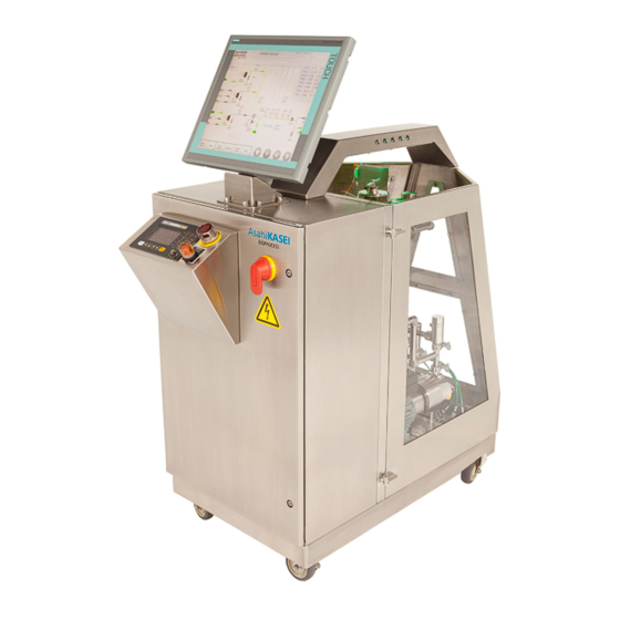
- Page 1 IBD™ 1K Inline Buffer Dilution System User Manual AEE33X01 Version 1.0 Issued April 22, 2015 Manufactured by Asahi Kasei Bioprocess America, Inc. 1855 Elmdale Avenue Glenview, IL 60026 USA *** TeDIS Valid on Date Printed Printed on: 18-09-2023 07:45:43 ***...
- Page 2 The release to a third party or the reproduction of content contained herein is expressly forbidden without the written authorization of Asahi Kasei Bioprocess America, Inc. *** TeDIS Valid on Date Printed Printed on: 18-09-2023 07:45:43 ***...
-
Page 3: Table Of Contents
Contents 1. Introduction ..........................1 2. Products Covered ........................1 2.1. Specifications ........................2 3. Important User Information ....................3 3.1. Intended Use ........................3 3.2. Regulatory Information ....................3 3.3. Safety Notices ......................... 4 3.4. Guide to User Manual Conventions ................4 4. - Page 4 5.10. Change Selected Method .................... 21 5.11. Copy Selected Method ....................21 6. Manual Method Programming ..................... 22 6.1. Method Parameters ....................... 22 6.2. Step Type ........................22 6.3. Step Name ........................23 6.4. Toggle Edit Mode ......................23 6.5. Preprogrammed Sequences ................... 23 6.6.
- Page 5 Table 2-1. Options and catalog numbers for IBD 1K System ................1 Table 3-1. Standards with which the IBD 1K System complies ................3 Table 4-1. Site requirements for installing and using the IBD 1K System ............7 Table 4-2. Low voltage input ..........................9 Table 4-3.
- Page 6 Figure 8-2. Simulation screen ..........................35 Figure 8-3. System Settings for probes ........................ 36 Figure 8-4. Alarm History showing the lists of alarms ..................37 Figure 8-5. Queues screen ........................... 38 Figure 8-6. Queue Editor screen .......................... 39 Figure 8-7. User Administration screen for making changes to user parameters ..........40 Figure 8-8.
-
Page 7: Introduction
Tel: +1-847-556-9700 or 1-800-865-4100 Fax: +1-847-556-9701 2. Products Covered The IBD 1K System is available with the following options (Table 2-1). Please note that pH control is included standard in all models. Table 2-1. Options and catalog numbers for IBD 1K System... -
Page 8: Specifications
Products Covered AEE33X01-1.0 2.1. Specifications Item Parameter Operating System flow rate range 60 to 1000 L/h Dilution range Up to 20 X (see Table 1) Accuracy ±2% FS (±1% when properly tuned) Line size 3/4 in. (WFI inlet), 1/2 in. (buffer 1 inlet), 1/2 in. -
Page 9: Important User Information
User Manual before installing, using, calibrating or maintaining the instrument. Always keep the User Manual at hand when using the IBD 1K System. Do not operate the IBD 1K System in any other way than is described in the user documentation. If you do so, you may be exposed to hazards that can lead to personal injury, and you may cause damage to the equipment. -
Page 10: Safety Notices
4.1. Risk Assessment The IBD 1K System has been designed and manufactured to provide a high level of personal safety. However, the residual risk is highly dependent on the application and environment in IBD™... -
Page 11: General Precautions
Getting Started AEE33X01-1.0 which the IBD 1K System is operated. In order to determine the safe operation of the equipment, a risk assessment must be made. This risk assessment, in combination with local regulations and policies, will result in specific safety instructions for installation, operation and maintenance, use of proper personal protective equipment, or other arrangements that are needed to operate your process safely. - Page 12 Getting Started AEE33X01-1.0 Table 4-1. IBD™ 1K Inline Buffer Dilution System User Manual Page 6 of 51 *** TeDIS Valid on Date Printed Printed on: 18-09-2023 07:45:43 ***...
-
Page 13: Installing And Moving The Ibd-1K
Getting Started AEE33X01-1.0 Table 4-1. Site requirements for installing and using the IBD 1K System Parameter Requirement Dual Input: 1) 480 VAC 3PH, 60 Hz Electrical power 2) 120 VAC 1PH, 60 Hz Ambient temperature 15 to 30 °C Connections... -
Page 14: System Operation
4.7. System operation CAUTION The working back pressure of the IBD 1K System should never exceed 3 bar, otherwise the safety relief devices on the individual pumps may lift and there is a risk of the buffer proportion being compromised. Always use appropriate pressure alarms, pressure vents and safety equipment. -
Page 15: Labels
1K System. 4.9.1. Electrical enclosure labels The IBD 1K System has dual power sources, each power source having its own utility cable and plug. The labels for each power source are located on the interior of the electrical panel door: low voltage input (Table 4-2) and high voltage input (Table 4-3). -
Page 16: Emergency Procedures
Do not defeat power switch. 4.10. Emergency Procedures This section describes how to shut down the IBD 1K System in an emergency. The section also describes the result in the event of power failure. 4.10.1. Emergency shutdown of IBD 1K System In an emergency situation, press the Emergency Stop button on the IBD 1K System to stop all function and potential energy (Figure 4-1). -
Page 17: Handling Power Failure
The software is designed to allow the user to control and configure blending of buffers and pH adjustment in any combination through 6 inlets and (up to) 6 outlets on the IBD 1K System. The system is operated from the locally installed industrial touchscreen interface in conjunction with the panel mounted Optek C8000 controller. -
Page 18: Startup
General Operation AEE33X01-1.0 Ethernet which coordinates logical sequence programming, trending and report generation. This manual describes the Windows 7 embedded process control software and interface built on Siemens WIN CC configuration software and custom built Trend and Report generation software. 5.1. -
Page 20: Process Overview Screen
General Operation AEE33X01-1.0 5.4. Process Overview Screen The Process Overview screen (Figure 5-2) is the home page for starting a batch, enabling the scheduler and viewing the status of a run. It has the Method name information at the top right, a footer at the bottom which is common to all screens. -
Page 21: Trend
General Operation AEE33X01-1.0 Process Overview screen is also used in manual mode to determine preset pump speeds for the automated run mode. Both of these will be discussed in the following beginning with the manual mode features. 5.5. Trend The trend screen (Figure 5-3) allows the Operator to view the real time data from an Auto run. -
Page 22: Figure 5-4. Multiple Trends Windows
General Operation AEE33X01-1.0 Figure 5-4. Multiple Trends windows Multiple Trends can be overlaid by opening another batch in <File><Open Batch> and configuring the pens for display. If the current batch file is not launched when you Show Trend, you can check for running batch much like opening another batch (Figure 5-5). IBD™... -
Page 23: Process Overview Screen, Manual Mode Without Feedback
Figure 5-5. Check for a running batch from the Data Analysis Tool software 5.6. Process Overview Screen, Manual Mode without Feedback The Process Overview screen is the home page for manual mode operation of the IBD 1K System with or without feedback. To place the system in manual mode, unhighlight the “AUTO”... -
Page 24: Process Overview Screen, Manual Mode With Feedback
General Operation AEE33X01-1.0 Figure 5-6. Designing a manual method by setting control of valves 5.7. Process Overview Screen, Manual Mode with Feedback The feedback control is activated by selecting a feedback bubble (FQIC001, AIC001, etc.) and selecting from the “PID Output linked to” to dropdown and select the pump of choice in the Process Overview (Figure 5-7). -
Page 25: Process Overview Screen, Auto Mode
General Operation AEE33X01-1.0 Figure 5-7. Process Overview control screen 5.8. Process Overview Screen, Auto Mode The Process Overview screen is the home page for starting a batch and viewing the status of a run. It has the Method name information at the top right, a footer at the bottom which is common to all screens. -
Page 26: Batch Screen
General Operation AEE33X01-1.0 5.9. Batch Screen The batch screen allows a unique Batch Name to be entered along with a carryover or unique Description and a Project Name (Figure 5-8). The Batch screen is also where a new method is selected by choosing to Change Selected Method or the current method can be copied and modified as a new method by selecting Copy Selected Method. -
Page 27: Change Selected Method
General Operation AEE33X01-1.0 5.10. Change Selected Method Change Selected Method brings up a list of 200 Methods to select from (Figure 5-9). The Methods are presented as 20 on a page with 10 pages accessible by pressing the Next or Previous buttons. -
Page 28: Manual Method Programming
Manual Method Programming AEE33X01-1.0 6. Manual Method Programming 6.1. Method Parameters In Method Parameters, the Administrator (or Operator with permissions) may modify the Method (Figure 6-1). The first option at their disposal is to change the identity of the inlet connections and/or the name of the Method by selecting the Method Parameters button on the Batch screen. -
Page 29: Step Name
Manual Method Programming AEE33X01-1.0 6.3. Step Name In the Method Steps, the Step Name is provided to clarify the purpose of the Step Type. Step Type, in the example of Prime, can be used as a purge or you may wish to identify what is being primed or purged. -
Page 30: Figure 6-3. Step Parameters Screen For Controlling Steps (Cip)
Manual Method Programming AEE33X01-1.0 boxes for Flow 1 and Flow 2 (L/min) and defines the outlet stream for the prime step only. Flow 1 and Flow 2 (L/min) are the throughput flow rates for the two diameters of tubing, 3/4 in. -
Page 31: Figure 6-4. Step Parameters Screen For Setting Limits (Cip)
Manual Method Programming AEE33X01-1.0 Figure 6-4. Step Parameters screen for setting limits (CIP) The CIP sequence is setup in three screens, Alarms, Limits and PID. The CIP sequence anticipates either a flooded system or an empty system which needs to be filled and flushed. Priming / flushing of the system is initiated as the first step in the CIP sequence by populating the Prime Time, (Inlet 1) box with an appropriate time to fill and initially flush the system. -
Page 32: Step Type Pause, Parameters
Manual Method Programming AEE33X01-1.0 6.6. Step Type Pause, Parameters Pause is a simple step where an interruption to the process may be introduced with the option of displaying a message (or not). The Pause duration and Message (set in Method Parameters) can be set (Figure 6-5). -
Page 33: Figure 6-6. Step Parameters Screen Showing Prime Input Steps
Manual Method Programming AEE33X01-1.0 Figure 6-6. Step Parameters screen showing prime input steps The Step Type Prime is confirmed in the Step Parameters screen along with the Outlet valve. The regulator is always time. The Alarm Table can be configured for specific application but generally just the Pressure is monitored. -
Page 34: Step Parameters
Manual Method Programming AEE33X01-1.0 Figure 6-7. Step Parameters screen showing limits The Prime step is effective in equilibrating an Inlet valve and associated pump for use. Please note: if there is air in the system and a strong backpressure has been set on BPV001, the pump will have a hard time self-priming. -
Page 35: Figure 6-8. Step Parameters Screen Showing Alarms
Manual Method Programming AEE33X01-1.0 In Step Parameters Alarms, at the top, the Step Index is displayed. This is the step in the series of steps of the current Method. The Step Type (Inline Dilution) is confirmed and an option is provided for regulating the product-in-spec by volume or time. The Regulator Limit will adjust to the selection of volume or time (minutes or liters). -
Page 36: Step Parameters Pid
Manual Method Programming AEE33X01-1.0 The options for “Control Blend” feedback are None, Flow control, pH control, and Conductivity control for buffer 1 and buffer 2. The column Blend Setpoint specifies the target value for that control loop. The System Flowrate column comes into play whenever a control option other than flow control is selected for Inlets 2-4 (Buffer 1) or Inlets 5-7 (Buffer 2). -
Page 37: Figure 6-9. Step Parameters Screen Showing How To Set Proportional And Integral Values
Manual Method Programming AEE33X01-1.0 Figure 6-9. Step Parameters screen showing how to set proportional and integral values The proportional (P) and integral (I) values are related to the chemistry of the solution you are blending, the response of the feedback analyzer, the system volume and the total flowrate. In the example above, pH and Conductivity were chosen as feedback on pumps 2&3 leaving Total Flow as a setpoint for pump 1 to achieve (as previously mentioned). -
Page 38: Batch Reports
Batch Reports AEE33X01-1.0 Conductivity 1 (Cond 1) and conductivity 2 (Cond 2) both have the option of being direct or reverse acting. Direct is where an increase in buffer concentrate causes an increase in conductivity. This is the usual situation. In the rare situation you wish to make blends which are near saturation, we have developed a trick where the near saturated buffer concentrate can be connected to Inlet 1 and Inlets 2-7 can be used to slightly dilute the near saturated solution. -
Page 39: Advanced Features
Advanced Features AEE33X01-1.0 Figure 7-1. Batch Reports search result Batch Reports Search By provides the option of searching by Batch ID or by Batch Date (Figure 7-1). Start Date changes to Batch ID when Batch ID is selected. When Start Date and End date are populated and the Search button is pressed, a list of all batch reports between those dates are listed. -
Page 40: Simulation Mode
Advanced Features AEE33X01-1.0 Figure 8-1. Advanced menu screen 8.1. Simulation Mode Simulation mode is provided for developing and testing the control code and operational performance without the need to run pumps and flow liquids, etc. All inputs and outputs can be simulated. -
Page 41: Audit Viewer
Advanced Features AEE33X01-1.0 Figure 8-2. Simulation screen 8.2. Audit Viewer Audit Viewer shows a list of auditable actions for the current, running Method. The Audit trail is stored in the sequel database and prints with the Batch Report 8.3. System Settings System Settings are provided for adjustable range output devices such as the Optek 8000 transmitter. -
Page 42: Alarm History
Figure 8-3. System Settings for probes 8.4. Alarm History The following alarms are programmed into the IBD 1K System (Table 8-1). Some alarms are only active during certain critical steps, while others can never be disabled. In the event of an alarm, check these common causes, as well the troubleshooting suggestions for remedying the problem. -
Page 43: Figure 8-4. Alarm History Showing The Lists Of Alarms
Advanced Features AEE33X01-1.0 The Alarm History is registered to a protected file and displays all actions and alarms from the beginning of time (Figure 8-4). Figure 8-4. Alarm History showing the lists of alarms Active Queue is where the status of the active queue is displayed. The Scheduler feature will run in sequence the Methods selected in the Active Queue and display the status. -
Page 44: Queue Editor
Advanced Features AEE33X01-1.0 Figure 8-5. Queues screen 8.5. Queue Editor By pressing the Edit button across from the queue of interest, you gain access to the Queue Editor screen (Figure 8-6) for programing the named Queue. In the Queue Editor you can configure the sequence of the queue by Add(ing), Delete(ing), Move(ing) Methods within the Queue. -
Page 45: Figure 8-6. Queue Editor Screen
Advanced Features AEE33X01-1.0 Figure 8-6. Queue Editor screen Enable Scheduler is where the queue sequence programmed in Queue and Queue Editor is enabled to be run in sequence. This button also appears on the Process Overview Screen. On the Process Overview Screen the Scheduler Enabled is displayed. The system must be in AUTO for a scheduled method to run on queue. -
Page 46: Figure 8-7. User Administration Screen For Making Changes To User Parameters
Advanced Features AEE33X01-1.0 Figure 8-7. User Administration screen for making changes to user parameters The software comes with default security settings that include four User types. Each User type has a different set of privileges and access capabilities within the software. The matrix shown in Table 8-2 shows the default settings for User security. -
Page 47: Date & Time
Advanced Features AEE33X01-1.0 Table 8-2. User matrix settings Level D Level C Level B Level A Privilege AKB / Admin Engineer Supervisor Operator Pause the system during all test steps Add new Windows user & assign passwords Access the method editor to change parameters Shutdown WIN CC Change PID parameters during a run Change Alarm Parameters from HMI... -
Page 48: Process Alarms Button Footer
Advanced Features AEE33X01-1.0 Figure 8-8. Date Time screen for setting time and date 8.7. Process Alarms Button Footer Process Alarms Button Footer is a quick view button of Process Alarm settings. 8.8. Steps Alarms Button Footer Steps Button Footer is a quick view button of the Method Steps Running. During an AUTO run, the Steps Button presents a view of the sequence of steps with the current Step highlighted by a progress bar (Figure 8-9). -
Page 49: Developing And Running A Method
Developing and Running a Method AEE33X01-1.0 Figure 8-9. Running Steps screen The Step Parameters for that step are presented by pressing the Parameters button. 9. Developing and Running a Method There are two modes of operation to assist in developing the pump speed presets and PID values for the control blend;... -
Page 50: Manual Presets
Developing and Running a Method AEE33X01-1.0 Operator, the Method(s) must be developed by Engineers having privilege level C or D. Engineers having privilege level C or D would be advised to first makeup sufficient buffer concentrate and pH tempering solution to develop the presets of the blend to the target setpoints in manual or semi-automatic mode. -
Page 51: Semi-Automatic Manual Presets
Developing and Running a Method AEE33X01-1.0 the semi-automatic mode for tuning PID values or directly to the Method where the PID tuning can be done on the fly with the proper permissions. 9.2. Semi-Automatic Manual Presets From the Process Overview screen, click (touch) on control bubbles to bring up windows which allow the pumps to be Started / Stopped and the Control Loops (PID Output Linked to) to be configured. -
Page 52: Naming Method / Inlets / Outlets
Developing and Running a Method AEE33X01-1.0 The presets manually determined in the bullet list above (Manual Presets) are transferred to the Method and are essential for rapid equilibration and providing the PID controller a reduced offset from setpoint so it can efficiently bring the system into control. Without these presets, the PID would have to find its way by first overshooting and then rebounding into control. -
Page 53: Running A Method
References AEE33X01-1.0 • Blend Setpoint, Cond1 = 1.3 • Blend setpoint, pH = 5.5 Alarms are in the first view of the Step parameters screen and for the Control Blend to make a decision on the product being In Spec, the Dead Band Over (DBO) and Dead Band Under (DBU) must be populated: •... -
Page 54: Appendix A: 21Cfr Part 11 Capability
AEE33X01-1.0 Appendix A: 21CFR Part 11 Capability The Asahi Kasei Bioprocess Process Control Software is designed to be 21 CFR Part 11 capable. The software includes passwords, complete and secure electronic audit trails, locked-down databases for both analog trend data and method data, system- and application- level security, and electronic signatures to provide full 21 CFR Part 11 capability. - Page 55 References AEE33X01-1.0 a. Each electronic signature shall be unique to one individual and shall not be reused by, or reassigned to, anyone else. § 11.200 Electronic signature components and controls a. Electronic signatures…shall: (1) Employ at least two distinct identification components such as an identification code and password.
-
Page 56: Appendix B: Data
References AEE33X01-1.0 Appendix B: Data P001 Pump Flow vs. Backpressure y = 0.1749x + 0.2166 y = 0.1714x + 0.1405 y = 0.165x + 0.12 y = 0.1593x + 0.0637 0 Barg Backpressure 1 Barg Backpressure 2 Barg Backpressure 3 Barg Backpressure Pump % Figure. -
Page 57: Appendix C: System Data Backup And Restore Procedure
References AEE33X01-1.0 Appendix C: System Data Backup and Restore Procedure PLC Back up Procedure 1. Start the connected PLC software using Siemens TIA portal V13. 2. Go on line with the PLC and HMI 3. Open the project in TIA portal 4. - Page 58 Email: info.eu@ak-bio.com Email: info.jp@ak-bio.com Visit us on the web at www.ak-bio.com IBD is a trademark of Asahi Kasei Bioprocess America, Inc. 2015 Asahi Kasei Bioprocess America, Inc. All rights reserved. *** TeDIS Valid on Date Printed Printed on: 18-09-2023 07:45:43 ***...
Need help?
Do you have a question about the IBD 1K and is the answer not in the manual?
Questions and answers