Table of Contents
Advertisement
Quick Links
Advertisement
Table of Contents

Summary of Contents for marposs M32A
- Page 1 MIDA ARM INTERFACE USER MANUAL Manual code D31027CG01...
- Page 2 The information and descriptions contained in this manual are provided in good faith and MARPOSS declares that they are accurate at the date of publication. MARPOSS is not obliged to update the contents or to inform its customers of changes to the product.
- Page 3 Failure to dispose of this product in accordance with these indications is punishable in accordance with the applicable laws. ABOUT THE DIRECTIVE “ROHS” REGULATING THE PRESENCE OF CERTAIN HAZARDOUS SUBSTANCES IN ELECTRICAL AND MARPOSS ELECTRONIC EQUIPMENT http://www.marposs.com/compliance_detail.php/eng/rohs ABOUT POSSIBLE USE IN MARPOSS PRODUCTS OF MATERIALS COMING FROM CONFLICT AREAS, REFER TO: http://www.marposs.com/compliance_detail.php/eng/conflict_minerals - User Manual...
-
Page 4: Table Of Contents
Index STANDARDS AND WARNINGS Description of the manual ........................5 Original version ............................ 5 Final test and warranty ......................... 5 General safety indications............Errore. Il segnalibro non è definito. Key to symbols ................Errore. Il segnalibro non è definito. Technical Assistance ........................... 6 GENERAL DESCRIPTION AND TECHNICAL DATA Technical specification ......................... -
Page 5: Standards And Warnings
1.2 Original version This document was originally issued in Italian language. Should there be any disputes due to the translations, even if made by MARPOSS the reference text will be the Italian version only. 1.3 Final test and warranty The company's warranty covers the faults in materials and execution: •... -
Page 6: General Safety Indications
1-1). The correct reference ensures quick and accurate answers. In the event of a fault condition that requires the assistance of Marposs personnel, contact the nearest service centre (visit the website www.marposs.com for a list of distributors). If any operations carried out on the product without written authorisation of the manufacturer, or performed in such a way as to compromise its correct operation or modify its specifications, the manufacturer declines all responsibility in the event the application fails to function correctly. -
Page 7: General Description And Technical Data
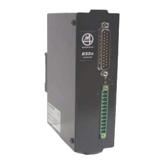
2. GENERAL DESCRIPTION AND TECHNICAL DATA The E32A SSR is a manually or electrically operated, specific interface for tool presetting arms on MIDA- SET (removable) end MIDA TOOL EYE (resident) lathes. It processes the signal generated by the touch probe so that it can be used by the machine tool, and manages the control signals; it also controls the Mida Electrical Tool Eye arm driver motor. -
Page 8: Technical Specification
2.1 Technical specification Logic circuits power supply Vdc =24 VDC SELV type (19.2 to 30 VDC) (ripple max 5%); 0.5 A (max) Motor power supply Vdc = 24 V DC SELV type (19.2 to 30 VDC) (ripple max 5%); 1.85 A (max) Outputs power supply (if supplied Maximum current 100 mA for each output from separate source) -
Page 9: Operating Characteristics
2.3 Operating characteristics In addition to the code (shown in the side label), it is possible to tell whether the E32A SSR is the Manual or Electrical version by the label on the front. In addition to the identification labels and the J1 and J2 connection connectors, there are two signaling LEDs: Yellow (L1): the touch probe status:... - Page 10 This is a white page User Manual...
-
Page 11: Using The E32A Ssr Interface
3. USING THE E32A SSR INTERFACE 3.1 Enabling the output: PROBE OUTPUT signal The output can be enabled using the ENABLE P.O. input signal. This signal enables the user to control the P.O. output (by selecting the TRUE/FALSE logic level) even when the measurement cycle is not running. Enable P.O. -
Page 12: Alternative Mida Set Arm Cycle Diagram (Enable P.o. =Aro)
3.1.2 Alternative MIDA SET arm cycle diagram (Enable P.O. =ARO) TRUE FALSE TRUE FALSE TRUE FALSE Probe enabled (measurement cycle) ARO = Arm ready for measurement MRO = Arm at rest P.O. = PROBE OUTPUT Figure 3-2. Enable output MODE 2 – operating cycle diagram. N.B. -
Page 13: Manual Mida Tool Eye Arm Cycle Diagram (Enable P.o. =True)
3.1.3 Manual MIDA TOOL EYE arm cycle diagram (Enable P.O. =TRUE) TRUE FALSE TRUE FALSE TRUE FALSE Probe enabled (measurement cycle) TRUE ARO = Arm ready for measurement MRO = Arm at rest P.O. = PROBE OUTPUT Figure 3-3. Enable output MODE 1 – operating cycle diagram. - User Manual... -
Page 14: Alternative Manual Mida Tool Eye Arm Cycle Diagram (Enable P.o. = Aro)
3.1.4 Alternative Manual MIDA TOOL EYE arm cycle diagram (Enable P.O. = ARO) TRUE FALSE TRUE FALSE TRUE FALSE Probe enabled (measurement cycle) ARO = Arm ready for measurement MRO = Arm at rest P.O. = PROBE OUTPUT Figure 3-4. Enable output MODE 2 – operating cycle diagram. N.B. -
Page 15: Electrical Mida Tool Eye Arm Cycle Diagram (Enable P.o. =True)
3.1.5 Electrical MIDA TOOL EYE arm cycle diagram (Enable P.O. =TRUE) TRUE FALSE TRUE FALSE TRUE FALSE TRUE FALSE TRUE FALSE Probe enabled (measurement cycle) TRUE MRC =command for moving arm to rest position. MRO = arm at rest ARC = command for moving arm to measurement position ARO = arm ready for measurement P.O. -
Page 16: Alternative Electrical Mida Tool Eye Arm Cycle Diagram (Enable P.o.=Aro)
3.1.6 Alternative Electrical MIDA TOOL EYE arm cycle diagram (Enable P.O.=ARO) TRUE FALSE TRUE FALSE TRUE FALSE TRUE FALSE TRUE FALSE Probe enabled (measurement cycle) MRC =command for moving arm to rest position. MRO = arm at rest ARC = command for moving arm to measurement position ARO = arm ready for measurement P.O. -
Page 17: Other Functions
4. OTHER FUNCTIONS 4.1 Function Inhibit The function inhibit allows the user to disable touch signal processing. In other words, when Inhibit = TRUE, the output (P.O.) is held at the false logic value, even when the Touch probe is deflected (see case 1-2 in Figure 4-1). 1: INHIBIT=FALSE TRUE FALSE... -
Page 18: Delay And Skip Probe Output (Jp5-Jp6)
4.2 Delay and skip PROBE OUTPUT (JP5-JP6) The P.O. (Probe Output) can be set to normal, delay or skip mode using jumpers JP5 and JP6 on circuit board of Interface (see Figure 4-3). Remove the four screws and open the case in order to access it and Install Jumpers as shown in the Figure 4-3. -
Page 19: Recognising The Connected Arm
4.3 Recognising the connected arm When it is switched on, E32A SSR acquires the status of a series of input signals in order to identify the type of arm it is connected to, and then configures itself accordingly. The resulting configuration, that is maintained until the equipment is switched off, is indicated for 2 seconds by the 2 LEDs, that remain at the beginning switched off for 2 seconds and then flash in synchronous way, as follows: Arm type... - Page 20 This is a white page User Manual...
-
Page 21: Diagnostics
5. DIAGNOSTICS N.B. Any system faults or malfunctions are indicated by the E32A interface 5.1 E32A: Alarms Whenever an alarm condition is detected: The arm connected to E32A stops moving; the red LED L2 on the equipment case is illuminated; •... - Page 22 This is a white page User Manual...
-
Page 23: Definition Of Sink/Source And Ssr Connections
6. DEFINITION OF SINK/SOURCE AND SSR CONNECTIONS. Marposs electronic devices exchange information with the PLC/CNC via digital Input/Output signals. The output circuits can be viewed as “SWITCHES” while the input circuits can be viewed as “LOADS”. In order to meet the requirements of the various manufacturers and users, E32A SSR is equipped with two outputs, a SINK/SOURCE type and a solid state relay (SSR). - Page 24 User Manual...
- Page 25 Notes...
- Page 26 Printed in Italy...
Need help?
Do you have a question about the M32A and is the answer not in the manual?
Questions and answers