Table of Contents
Advertisement
Quick Links
Advertisement
Table of Contents

Subscribe to Our Youtube Channel
Related Manuals for Fimet Neo

Summary of Contents for Fimet Neo
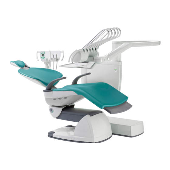
- Page 1 ® Fimet Neo Technical Manual Ver. 1.8 – 19.12.2018...
-
Page 2: Table Of Contents
Contents Introduction ..............................4 Manufacturer ............................4 Models Covered by this Manual ....................... 4 Directives and Standards ......................... 4 Terms and Abbreviations ......................... 4 Symbols and Markings ..........................5 Referred Documents ..........................6 General ..............................7 Transportation, Storage and Packaging ....................7 Environmental Specifications ......................... - Page 3 General Description ..........................39 System overview ............................ 39 Data communication ..........................41 Status LEDs ............................41 Connection Box............................41 Unit/Cuspidor ............................42 Chair ..............................42 Instrument Bridge ..........................42 Suction Head ............................42 6.10 User interference devices ........................43 6.11 Radio devices ............................
-
Page 4: Introduction
93/42/EEC of June 14, 1993 concerning medical devices. 1.3.1 Quality Standards Fimet Oy is a responsible dental manufacturer. The company’s quality management system is certified by notified body (VTT) according to the standards: SFS-EN ISO 13485:2012 Medical devices - Quality management system - System re-... -
Page 5: Symbols And Markings
Applied part Part of the equipment that in normal use necessarily comes into physical contact with the patient to perform its function. Applied parts in Neo system are: seat, backrest, headrest, footrest, handles, instruments, and suction tips. System Dental Treatment System, consisting of Dental Unit, Dental Chair, Operating Light, Foot Control, and Hand Control. -
Page 6: Referred Documents
Warning! This symbol warns against possible operating errors or hazards to the product, user, patient or maintenance personnel. Warning: High Voltage! This symbol warns against high voltage. The system has to be separated from mains volt- age before maintaining. Only qualified personnel may open the enclosure provided with this symbol. -
Page 7: General
General Warning!: If this equipment is modified, appropriate inspection and testing must be conducted to ensure continued safe use of the equipment. Contact the manufacturer for detailed descriptions on printed circuit boards, component lists, and other information and spare parts required to repair and service the equipment. Transportation, Storage and Packaging The patient chair and unit are delivered in separate packages. - Page 8 1.8.2 Contents of the chair package Order code Quantity Item Neo Chair 1 pc Seat upholstery 1 pc Backrest 1 pc Handle, right 1 pc Handle, left 1 pc Headrest 1 pc Remote foot control 1 pc Chair seat bottom back part...
- Page 9 1 pc O-ring OR156178 2 pcs O-ring OR12015 2 pcs Tray arm stopper, white(*) (w. double tray) 59205200W 1 pc Documents Fimet Neo User Guide 1 pc Instrument instruction manuals n pc(s) Neo Quick Guide 1 pc Technical Manual • 9...
-
Page 10: Environmental Specifications
Order code Quantity Item Neo Registration card 1 pc Neo Service book 1 pc Neo monitor and camera power cable connections(*) 1 pc * optional Environmental Specifications Variable During storage and transport Humidity Temperature -40°C 70°C Temperatures for display -20°C 60°C... -
Page 11: Movement Ranges
1.11 Movement Ranges Technical Manual • 11... -
Page 12: Installation
Installation Space Requirements 12 • Technical Manual... - Page 13 Technical Manual • 13...
-
Page 14: Unpacking
Unpacking 2.2.1 Unpacking the chair After cutting the bands, lift the cardboard hood away. Lift both of the trays away. Then lift the cardboard collar away. Unscrew the fixing screws. The chair is now ready to be positioned to the final location. The side of cardboard box can be used as a slide to ease up the positioning of the chair. -
Page 15: Attachment To Floor
Attachment to floor Remove screws A from both sides of the base. Then detach the back cover. Now two out of five attachment screws are accessible. Then push joystick inwards to uncover the screw hole. Then unscrew joystick attachment screw and detach the joystick by lifting it carefully. Technical Manual •... - Page 16 The C attachment screws are now accessible (4/5 in total). The last attachment screw (3) is under a cover which can be detached using a suitable tool, for example a coin. Figure 1: Attachment bolts The five attachment screws are located as shown in picture above. 16 •...
-
Page 17: Floor Materials
Floor materials The Fimet Neo can be attached to different kinds of floors; for example floors made of con- crete, wood, or gypsum. Table 2: Examples of attachments lists examples which are ac- ceptable. The following table (Table 1: Minimum withdrawal strengths) shows the required pulling strengths the attachment bolts have to withstand (withdrawal strengths). -
Page 18: Adapter Adjustments
Adapter adjustments Bright securing & adjusting hex screw Black attachment hex screw Figure 2: Adapter with bolts Attach the black hex screws. Adjust the cuspidor horizontally and vertically straight by loos- ening the corresponding attachment screws. Ensure that at least 8 mm of the threaded part of the bolt is inside the hole of the patient chair body plate. -
Page 19: Removing Transport Screw
Removing transport screw Electronics protection cover screw Figure 4: Electronics protection cover Unscrew the attachment screw and remove electronics protection cover. Transportation locking screw Figure 5: Transportation locking screw Loosen the transportation locking screw. This screw prevents the rotation of the cuspidor during transportation. -
Page 20: Adjusting The Stiffness Of Tray Rotation
Figure 6: Instrument Arm spring adjustment Remove the spring adjustment opening cover before adjusting the tension of the spring. This adjusts the balance and displacement force of the instrument arm. 2.11 Adjusting the stiffness of tray rotation Locking screw Adjustment screw Tray Arm The stiffness of the rotation of the tray arm is adjusted with the adjustment screw (shown on... -
Page 21: Setting Air And Water Pressures
2.13 Setting Air and Water Pressures The pressure regulators inside the connection box control the pressures in the system. The pressures must be set correctly. The pressure increases by rotating the level control clock- wise and decreases counter clockwise. The symbols for the gauges are: W-water and A-air. The recommended pressures are: Pressure level control... -
Page 22: Annual Service
Annual service Service steps Visual Inspection - General o Check that safety related markings and labels are legible and complete o Check the condition of mechanical parts o Check that there are no odours or visual impurities in the tubes and no stains on the surfaces o Check the condition of the power supply cord, air and water tubes o Check that user guide is accessible and is of correct version... -
Page 23: Greasing The Lift Motor Screw Spindle
o Check operation of the chair control buttons o Check operation of suction - high, low and both together o Check condition of suction hoses o Check the selective valves o Check the F1-filter o Check the suction arm o Check the bowl valve sensor o Check the bowl valve o Check the condition of silicon cover ... -
Page 24: Safety Measurements
The type of the red grease to use is: Fimet Spindle Grease. Available from Fimet Oy. Safety measurements These measurements must be done according to the standard IEC 62353:2007 Medical electrical equipment. Recurrent test and test after repair of medical electrical equipment. - Page 25 mains lines (connected together) and F-type applied part (if any) The maximum allowed currents are: Equipment Leakage Currents Applied Part Applied Accessible Part Type B Part Type Leakage currents 1 mA 5 mA 1 mA Mains part Applied part Supply Protective mains...
- Page 26 Mains part Applied part Ω Protective earth Figure 13: Measuring arrangement for insulation resistance between mains lines and protective earth Mains part Applied part Protective earth Ω Figure 14: Measuring arrangement for insulation resistance between applied parts and protective earth 26 •...
-
Page 27: Repairs And Adjustments
Repairs and adjustments Replacing Fuses Warning! Use only fuses with specified and marked characteristics. Replacing with an incorrect type may cause a fire in case of a short circuit. FST 5x20, 2A (or 3.15A) fuse 10 A, 10 A, 10 A, 10 A, 15 A, 10 A,... -
Page 28: Replacing Electric Circuit Boards
Replacing Electric Circuit Boards Warning: Do not replace the lithium battery on the master card but change the whole electric circuit board. Do not place the master card to a hot environment because of the danger of explosion of the battery. Replacing rechargeable batteries of remote foot control Power switch of the remote foot control... - Page 29 Code Description Source Display text Errors Chair Move Alarm MDR1 ALARM,CHAIR,LIFT MOVE Switch - Lift Chair Move Alarm MDR2 Switch – Back Chair Move Alarm Switch - Unit Under Voltage MDR1 MDR1,POWER,LOST Under Voltage MDR2 Under Voltage Under Voltage Under Voltage Under Voltage Under Voltage Under Voltage...
-
Page 30: Setting The Chair Movement Soft Limits
Button Down at Boot JOY2 Button Down at Boot Multiple Tool Selec- tion Dutycycle limitter FCC battery low Chair move limit Information FCC charger con- nected FCC charger discon- nected FCC battery full Timer Elapsed Flush Done Cattani Draining Net Traffic Failure System Unknown Message Factory testing... -
Page 31: Remote Foot Control Settings
Remote foot control settings Open the "SERVICE" menu, described in chapter 5 User interface - service menu. Select "CONFIG" and "RFC MODE". If the "DEF" is active, the foot controls settings are in the de- fault mode. The function of the foot control joystick and buttons can be altered by changing the "RFC CONF MODE"... -
Page 32: Remote Foot Control Lever Calibration
MDR1, lift motor E=Chair up, F=Chair down MDR2, tilt motor E=Backrest up, F=Backrest down MDR3, cart motor E=Cart up, F=Cart down D3 = Buttons E and MDR4, Trendelenburg motor E=Seat tilt, F=Seat horizontal MDR1‒, lift motor E=Chair down, F=Chair up (Default = --) MDR2‒, tilt motor E=Backrest down, F=Backrest up... -
Page 33: Setting The Parameters Of Joysticks
4.10 Setting the parameters of joysticks Side parameter defines the joysticks placement, either doctors or assistants side. Press and hold any two of the joystick’s micro switches simultaneously and plug in the joy- stick’s connector. If both LEDs are blinking, push the joystick towards the foot rest [B=raise the backrest]. -
Page 34: Faro Alya Operating Light On/Off Mode Change
RESET -button Figure 18: MST displaying “C0” 4.12 Faro Alya operating light On/Off mode change Faro Alya operates in two different modes. In mode 1 the light isn’t automatically switched on when the power is fed to the lamp. This mode allows the lamp to be controlled from the lamp’s own power switch. - Page 35 Figure 20: Faro Alya older electronics mode change The newer electronics, starting from serial number 10LD010816, has different procedure. To switch mode: • Put in the jumper J2 • Power on the board • Pull out jumper J2 Figure 21: Faro Alya newer electronics mode change Technical Manual •...
-
Page 36: User Interface - Service Menu
User interface - service menu To enter service menu, click and hold -button (about 2 secs.) until the following display appears: Then click within 3 seconds the -button. Menu item Submenu 1 Submenu 2 Submenu 3 Description +SYS INFO MESSAGES Error, info, and warn- ing message log MASTER... - Page 37 RESET MAX Resets the max value SET MEM Factory use only TESTER Factory use only BRIDGE TOOL POS SYRINGE / Sets the instrument TURBIN1 / type for each instru- TURBIN2 / ment module. =-sign TURBIN3/ marks the selected TURBIN4/ instrument type. MOTORF1 / MOTORF2 / MOTOR F3/...
- Page 38 CAT-PMP/ pump, wet line WETLINE SUC TIMES SUC MOTOR Suction motor time CAT FLUSH Cattani flushing time CAT PUMP Cattani pump time EVASEPT Evasept time CONFIG RFC MODE/ Remote foot control settings, operating LAMP MODE/ light control, joystick JOY MODE settings * Note, beep-signal confirms that the set value is stored To enter debug menu, click and hold...
-
Page 39: Electronics
Communication between the PCBs is realised with a data bus. This bus is used with all Neo PCBs. Bus data transfer is controlled by MST-card. There is no direct data transfer between two separate PCBs;... - Page 40 Technical Manual • 40...
-
Page 41: Data Communication
Data communication All the PCBs have the same communication electronics. It consists of a microcontroller, RS485 transceiver and two Molex 4-pin Spox connectors. The software of the microcontrol- ler utilizes dedicated UART registers to receive from and transmit data to the communica- tion bus. -
Page 42: Unit/Cuspidor
Separate multimedia power supply 28 VDC / 1A & 12 VDC / 4A for multimedia devices, isolated from main power supply Unit/Cuspidor Unit main PCB Valve control for cuspidor functions (tap(s), suction controls, etc.) Power source for operating light ... -
Page 43: User Interference Devices
6.10 User interference devices Includes keyboards, joysticks and displays, few different types Takes user inputs to control the device Gives information about the device status, from date/time to Alarm signals 6.10.1 Remote foot control Rechargeable batteries x4 ... -
Page 44: Pcb Descriptions
PCB descriptions ALA - Unit bottom safety switch 7.1.1 General description The safety switch opens when the unit is lowered against an obstacle. 7.1.2 Connectors Connector Purposed use ALARM UNT-card 7.1.3 Indicators ALB - Suction arm safety switch 7.2.1 General description The safety switch opens when the suction arm is lowered against an obstacle. -
Page 45: Ald - Chair Back Safety Switch
7.3.2 Connectors Connector Purposed use ALARM1 MDR-PCB, lift ALB-PCB, jumper if no suction arm (=no ALB) 7.3.3 Indicators ALD - Chair back safety switch 7.4.1 General description The safety switch opens when the chair back rest is lowered against an obstacle. 7.4.2 Connectors Connector... -
Page 46: Alf - Chair Movement Limiter Switch, Tilt
The movement limit switch gets closed on the mechanical limits of the seat lifting. 7.5.2 Connectors Connector Purposed use LIMITS MDR-card, lift 7.5.3 Indicators ALF - Chair movement limiter switch, tilt 7.6.1 General description The movement limit switch gets closed on the mechanical limits of the back rest tilting. 7.6.2 Connectors Connector... -
Page 47: Bui - Instrument Bridge User Interface
7.7.2 Connectors Connector Purposed use Reserved Reserved Tool selection switches, DSWs, HSWs Instrument light #1 Instrument light #2 Instrument light #3 Instrument light #4 Instrument light #5 NET1 Communication bus #1 NET2 Communication bus #2 PWR1 Power #1 PWR2 Power #2 INTERCON Bridge bus 7.7.3... -
Page 48: Bva - Instrument Bridge Valve Board A
7.8.2 Connectors Connector Purposed use Display (GUI) NET1 Communication bus #1 NET2 Communication bus #2 7.8.3 Indicators Colour Purposed use Green Status Power Yellow Button status Yellow Button status Yellow Button status Yellow Button status Yellow Button status BVA - Instrument bridge valve board A 7.9.1 General description 4 instrument line pilot valves for pneumatic block. -
Page 49: Bvb - Instrument Bridge Valve Board B
7.9.2 Connectors Connector Purposed use BVD-PCB 7.9.3 Indicators Colour Purposed use Yellow Valve status, open when lit Yellow Valve status, open when lit Yellow Valve status, open when lit Yellow Valve status, open when lit 7.10 BVB - Instrument bridge valve board B 7.10.1 General description Water, main air and cooling air valves for pneumatic block. -
Page 50: Bvd - Instrument Bridge Valve Board
Yellow Valve status, open when lit 7.11 BVD - Instrument bridge valve board 7.11.1 General description Controls 7 valves Relay output for scaler Optional relay output Bridge bus provides logic and supply voltage (32 VDC) to the board. 7.11.2 Connectors Connector Purposed use Scaler relay... -
Page 51: Cui - Chair User Interface
7.12.2 Indicators Colour Purposed use Yellow Communication bus power present 24 VDC present 7.12.3 Connectors Connector Purposed use UNIT UNT-PCB PWR3 MDR-PCB PWR4 MDR-PCB PWR7 Power 24 VDC PWR8 Power 24 VDC Emergency stopping device Emergency stopping device NET1 Communication bus NET2 Communication bus NET3... -
Page 52: Dsw - Doriot Tool Switch
7.13.2 Connectors Connector Purposed use DISP1 OLED Display Communication bus 7.13.3 Indicators Colour Purposed use Green Status Power 7.14 DSW – Doriot tool switch 7.14.1 General description The DSW card detects the doriot-arm position with optical port. The card passes the in- strument selection information to the BRI-card. -
Page 53: Hsw - Hanging Hose Switch
7.15.2 Connectors Connector Purposed use OLED DISP OLED-display BUI/SUI card 7.16 HSW - Hanging hose switch 7.16.1 General description The HSW card detects the hanging hoses position with optical port. The card passes the instrument selection information to the BRI-card. The tools switch includes microcontroller, IR-emitter diode, phototransistor, two indication LEDs and extend- and select connectors. -
Page 54: Mdr - Dc Motor Driver
7.17.2 Connectors Connector Purposed use NET1 Communication bus NET2 Communication bus 7.17.3 Indicators Colour Purposed use Green Status Power 7.18 MDR - DC motor driver 7.18.1 General description The MDR drives the lift and backrests motors. Two models are available, one for backrest and one for lift. - Page 55 7.18.2 Connectors Connector Purposed use MOTOR Motor connector MANUAL Manual driving of motor, connect 1&2 forward and 2&3 reverse LIMIT Limit switch, ALE / ALF -PCBs ALARM Safety switch, ALC / ALD -PCBs Position sensor potentiometer NET1 Communication bus NET2 Communication bus Power 1, power in, 4 pins Power 2, power out, 2 pins...
-
Page 56: Mst - Master Device Controller
7.19 MST – Master device controller 7.19.1 General description MST controls the communication bus and stores system configuration. The MST has a bat- tery-protected clock, two buttons and a two digit 7-segment display. When pressing the up- per button (COUNT) the amount of detected devices is shown. The lower button (RESET) rescans the devices in the system. -
Page 57: Pwrb Power Supply - Secondary
7.20.2 Connectors Connector Purposed use PWRB-PCB Main supply 7.21 PWRB Power Supply - Secondary 7.21.1 General description Generates voltages: 7 VDC 1A, 24VDC 15A, 32VDC 10A, 24VAC 5A, 12 VDC 2A. 7.21.2 Connectors Connector Purposed use TRANS-1 Transformer UNIT-1, UNIT-2 UNT-PCB, miscellaneous CHAIR-1, CHAIR-2 CNA-PCB... -
Page 58: Pwrc Power Supply - Multimedia
Colour Purposed use LED1 Communication bus over current protection (lit when over- LED2 24 VDC fuse condition indicator (lit when blown) LED3 12 VDC fuse condition indicator (lit when blown) LED4 32 VDC fuse condition indicator (lit when blown) LED5 24 VAC fuse condition indicator (lit when blown) 7.22 PWRC Power Supply - Multimedia... -
Page 59: Rfc - Radio Foot Controller
Connector Purposed use TSW1 RFT-PCB CON2 RFC-PCB 7.24 RFC – Radio foot controller 7.24.1 General description The RFC-PCB has a radio transceiver for wireless communication to the system. It has a 4- direction joystick, 2 buttons and 1 lever for instrument operation. Two LEDs show the radio status;... -
Page 60: Rly - Relay Card For External Connections
7.25.2 Connectors Connector Purposed use TSW2 RFB-PCB, welded 7.26 RLY – Relay card for external connections 7.26.1 General description The RLY-PCB controls external devices, for example suction motor, doorbell and lamp. 7.26.2 Connectors Connector Purposed use PWR1 Power connector PWR2 Power connector NET1 Communication bus... -
Page 61: Sui - Suction Head User Interface
RXC-PCB communicates with remote foot control (RFC), charges remote foot controller batteries and reports battery status to Master Device Controller (MST). When charging ca- ble is plugged in, the communication is done radiolessly via charging cable. The radio communication uses 2.4 GHz frequency band. 7.27.2 Connectors Connector... -
Page 62: Umb - Bien Air Micromotor Adapter
7.28.2 Connectors Connector Purposed use GUI connector NET1 Communication bus NET2 Communication bus Suction tool selection switches, HSWs 7.28.3 Indicators Colour Purposed use Yellow Button status Yellow Button status Yellow Button status Green Status Power 7.29 UMB – Bien Air micromotor adapter 7.29.1 General description UMB-PCB has a serial data adapter for Bien Air 3-phase micromotor controller and a relay... -
Page 63: Umf - Micromotor Driver
7.29.2 Connectors Connector Purposed use OUTPUT-1 Micromotor 1 OUTPUT-2 Micromotor 2 MOTOR INPUT Bien Air micromotor controller INTERCON Bridge bus PWR-OUT Bien Air micromotor controller (power) UMOTOR Bien Air micromotor controller (serial data) UMOTOR2 Reserved for other micromotor controllers 7.29.3 Indicators Colour Purposed use... -
Page 64: Unt - Unit Main Module
Connector Purposed use INTERCON Bridge bus MOTOR1 Micromotor 1 MOTOR2 Micromotor 2 MOTOR3 Micromotor 3 7.30.2 Indicators Colour Purposed use Green Status Power Yellow Activity 7.31 UNT – Unit main module 7.31.1 General description The UNT-PCB controls valves on UNV-PCB. It controls also auxiliary devices. 7.31.2 Connectors 64 •... -
Page 65: Unv - Unit Valves
Connector Purposed use VAL-A UNV-PCB VAL-B UNV-PCB BTL-IO Clean water bottle switch and LED SEN1 Water level sensor 1 SEN2 Water level sensor 2 META-RUN Metasys relay output ALARM ALA-PCB GEN-OUT General output (eg. Faro Alya control) VIDEO-CTR Video camera control AC-1 Power output, 24 VAC AC-2... -
Page 66: X1N10A - Pressure Relief
7.32.2 Connectors Connector Purposed use 7.32.3 Indicators Colour Purposed use LED1-9 Yellow Valve status, open when lit 7.33 X1N10A - Pressure relief 7.33.1 General description Relieves air and water pressures when the system is powered down. 7.33.2 Connectors Connector Purposed use CONNECTOR PWRB-PCB 66 •... -
Page 67: Pneumatics
Pneumatics Technical Manual • 67... - Page 68 68 • Technical Manual...
- Page 69 Technical Manual • 69...
- Page 70 70 • Technical Manual...
- Page 71 Technical Manual • 71...
- Page 72 72 • Technical Manual...
- Page 73 Technical Manual • 73...
- Page 74 74 • Technical Manual...
- Page 75 Technical Manual • 75...
- Page 76 76 • Technical Manual...
- Page 77 Technical Manual • 77...
- Page 78 78 • Technical Manual...
- Page 79 Technical Manual • 79...
- Page 80 80 • Technical Manual...
- Page 81 Technical Manual • 81...
- Page 82 82 • Technical Manual...
- Page 83 Technical Manual • 83...
- Page 84 84 • Technical Manual...
- Page 85 Technical Manual • 85...
- Page 86 86 • Technical Manual...
- Page 87 Technical Manual • 87...
- Page 88 88 • Technical Manual...
- Page 89 Technical Manual • 89...
- Page 90 90 • Technical Manual...
-
Page 91: Materials Used In Maintenance
Volume Order code Head rest lock mecha- Orapi CT 609 Grease 20 ml 3232135 nism Lift and tilt motor spin- Fimet Spindle Grease (Red) 20 ml REDGREASE3751P dles and gear wheels Rechargeable batteries Remote foot control 4 pcs 76502100X4 Rubber button set...
Need help?
Do you have a question about the Neo and is the answer not in the manual?
Questions and answers