
Summary of Contents for imoware USB421
- Page 1 Imoware USB421 USB 4-Port Roaming Mouse Switcher VER 1.0 The information contai ned in this document is non-contrac tual and is s ubject to change without notice...
-
Page 2: Table Of Contents
Thank you for purchasing this product For optimum performance and safety, please read these instructions carefully before connecting, operating or adjusting this product. Please keep this manual for future reference. Surge protection device recommended This product contains sensitive electrical components that may be damaged by electrical spikes, surges, electric shock, lighting strikes, etc. -
Page 3: Introduction
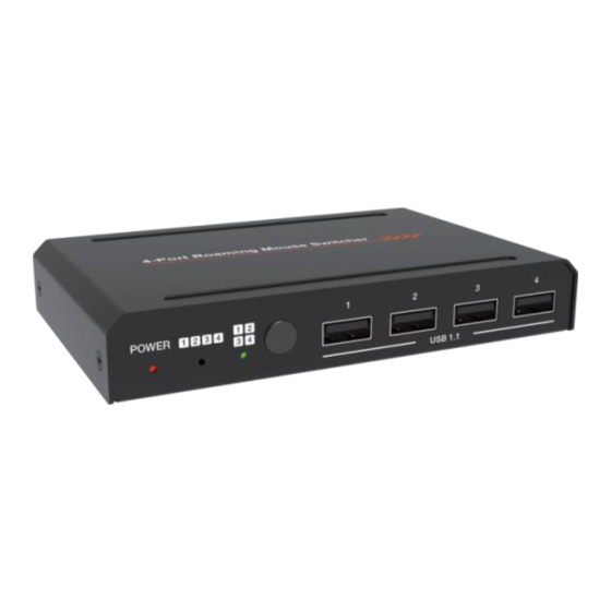
1. Introduction This USB 4-Port Roaming Mouse Switcher can realize that 4-port USB1.1 keyboard and mouse or other peripherals share four computer hosts. It supports Mouse Slide Screen Function with three modes (Mode 1, Mode 2 and User Defined Mode). Built-in Web GUI can set Synchronous Control Function (One set of keyboard and mouse can control all connected computers simultaneously). -
Page 4: Specifications
4. Specifications Technical USB Version USB 1.1 Data Transfer Up to 12Mbps (1.5MB/S) Rate Human-body Model: ±8kV (Air-gap discharge), ESD Protection ±4kV (Contact discharge) Connection Input 4 x USB [Type A] Output 4 x USB [Type B] 1 x RS-232 [Phoenix connector] Control 1 x LAN [RJ45] Mechanical... -
Page 5: Operation Controls And Functions
5. Operation Controls and Functions 5.1 Front Panel Name Function Description 1 POWER LED When the product is powered on, red power LED will be on. When Mode 1 (Mouse left and right cross screen) is selected, the 2 Mode 1 LED green LED will be on. -
Page 6: Rear Panel
5.2 Rear Panel Name Function Description DC 5V DC 5V/1A power input port. Four USB signal input ports, connecting to four computer PC 1-4 ports hosts with USB cables. Network port, connecting to the main control computer with network cable. RS-232 serial port, connecting to a PC or control system RS-232 with a 3-pin phoenix connector cable to transmit RS-232... - Page 7 IP:192.168.62.105 in the above figure is the IP Address of the switcher (the IP address is variable, depending on what the specific machine returns). Step 2: Connect the LAN port of the switcher to a PC with an UTP cable, and set the IP address of the PC to be in the same network segment with the switcher.
- Page 8 Select the Username from the list and enter the password. The default passwords are: Username User Admin Password user admin After entering the password, click the “LOGIN” button and the following Status page will appear. ■ Status Page The Status page provides basic information about the product model, firmware version, hostname and the network settings of the device.
- Page 9 ■ Mode Page ① Swipe and Sync Function Select: Click either one to switch between the Mouse Slide Screen Function (default) or Synchronous Control Function (One set of keyboard and mouse can control all connected computers simultaneously). ② Hotkey Setting: Click on any item to select the keyboard hotkeys. ③...
- Page 10 ■ Network Page Set the Default Network Click “Set Network Defaults” button, there will be a prompt, as shown in the following figure: Click “OK” to search the IP Address again, as shown in the following figure: 8/11...
- Page 11 After searching is completed, it will switch to the login page, the default network setting is completed. Modify User Password Click the “User” button, enter the correct Old Password, New Password, and Confirm Password, then click “Save”. After successful modification, there will be a prompt, as shown in the following figure: Note: Input rules for changing passwords: (1) The password can’t be empty.
- Page 12 The value ranges of each parameter are as follows Parameter Range Value IP Address 1.0.0.1~223.255.255.254 The first three digits of the Gateway must be the same as the first Gateway three digits of the IP address. The last digit ranges from 1 to 254. Subnet Mask Subnet Mask is not allowed to set 0.0.0.0/255.255.255.255.
-
Page 13: Application Example
7. Application Example 11/11...
Need help?
Do you have a question about the USB421 and is the answer not in the manual?
Questions and answers