Table of Contents
Advertisement
Quick Links
Advertisement
Table of Contents

Subscribe to Our Youtube Channel
Related Manuals for Jung 214201SR


Summary of Contents for Jung 214201SR
- Page 1 Operating instructions Area / line coupler Art. no. 214201SR ALBRECHT JUNG GMBH & CO. KG Volmestraße 1 58579 Schalksmühle GERMANY Telefon: +49 2355 806-0 Telefax: +49 2355 806-204 kundencenter@jung.de 27.09.2023 82408203 J0082408203 www.jung.de...
-
Page 2: Table Of Contents
Area / line coupler Table of contents Safety instructions ...................... 3 System information ...................... 3 Device components ...................... 4 Intended use ........................ 5 Product characteristics ..................... 5 Area of use ........................ 6 Backbone coupler and line coupler................ 6 Segment coupler and amplifier ................ 7 Operation .......................... -
Page 3: Safety Instructions
The device can be updated. Firmware can be easily updated with the Jung ETS Ser- vice App (additional software). The device is KNX Data Secure capable. KNX Data Secure offers protection against manipulation in building automation and can be configured in the ETS project. -
Page 4: Device Components
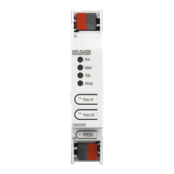
Area / line coupler Device components Figure 1: Front view KNX device connection terminal, subordinate lineSL Status LED Run Status LED Main Status LED Sub Status LED Mode Button Pass IA Button Pass GA Programming LED, red Programming button PROG. KNX device connection terminal, higher-order line ML (10) Status LED function Run Power failure on higher-order line... -
Page 5: Intended Use
Area / line coupler The display of errors has a higher priority. Status LED function Sub Lights up orange for 6 ms Telegram reception, subordinate line Lights up red for 6 ms One-time communication error, subordinate line Lights up red for 100 ms Repeated communication error, subordinate line The display of errors has a higher priority. -
Page 6: Area Of Use
Area / line coupler Area of use Backbone coupler and line coupler SV DR Figure 2: Use as a backbone and line coupler Backbone coupler (BK): The physical address is the address of a backbone coupler X.0.0 and must match the logical topology of the KNX system. Connection of a main line (HL) with a backbone line (BL). -
Page 7: Segment Coupler And Amplifier
Area / line coupler Segment coupler and amplifier SV DR SV DR SV DR SV DR Figure 3: Use as a segment coupler and amplifier Segment coupler (SK): The physical address is the address of a normal KNX parti- cipant X.Y.Z (Z≠0) and must match the logical topology of the KNX system. Division of a line (max. -
Page 8: Information For Electrically Skilled Persons
Area / line coupler The status LED Run displays the state of the filter functions, (see figure 1). The filter is deactivated until the Pass IA button is pressed again. Deactivating the group address filter function ■ Press the Pass GA button. The status LED Mode briefly lights up red. -
Page 9: Commissioning
Area / line coupler Commissioning Programming the physical address and application programme with ETS ■ Switch on the bus voltage. ■ Press the programming button (9) PROG.. The programming LED (8) lights up. ■ Programming the physical address. The programming LED goes out. ■... -
Page 10: Technical Data
5 s. Restoring the device to factory settings The device can be reset to factory settings with the Jung ETS Service App. This function uses the firmware contained in the device that was active at the time of de- livery (delivered state). - Page 11 Area / line coupler kundencenter@jung.de www.jung.de 82408203 11 / 11 27.09.2023 J0082408203...
Need help?
Do you have a question about the 214201SR and is the answer not in the manual?
Questions and answers