Table of Contents
Advertisement
Quick Links
Advertisement
Table of Contents

Summary of Contents for Piusi MC BOX ac AGILIS
- Page 1 MC BOX ac Installation, use and maintenance BULLETIN M0649 EN_...
- Page 2 Installation, use and maintenance ENGLISH Bulletin M0649 2 / 68 M0649...
-
Page 3: Table Of Contents
RS485 serial data connection: ....................... 26 13 GETTING TO KNOW MC BOX .....................27 13 1 OPERATING MODES..............................27 13.1.1 SYSTEM MODE ............................27 3/124 3 / 68 This manual is the property of PIUSI S.p.A. Whole or partial reproduction of this manual is forbidden. - Page 4 Installation, use and maintenance 13.1.2 DISPENSING MODE ..........................27 13 2 DISPLAYS ..................................27 13.2.1 NUMERIC DISPLAY ............................ 27 13.2.2 ALPHANUMERIC DISPLAY ........................27 13 3 KEYPAD .....................................28 13 4 SPECIAL KEY COMBINATIONS ..........................28 13 5 ELECTRONIC KEYS AND THE READER ......................28 14 USING MC BOX ........................
-
Page 5: General Precautions
THIS MANUAL BELONGS TO PIUSI S.p.A. All rights for reproduction are reserved for PIUSI S.p.A. The text cannot be used in other printed documents unless expressly authorised in written form by PIUSI S.p.A. © PIUSI S.p.A. - WHOLE OR PARTIAL REPRODUCTION OF THIS MANUAL IS FORBIDDEN. -
Page 6: Eu Declaration Of Conformity
- - Radio Equipment Directive (RED) 2014/53/EU The technical file is at the disposal of the competent authorities in response to a motivated request made to PIUSI S.p.A. PRODUCT or further to a request sent by e-mail to: doc_tec@piusi.com. THE ORIGINAL DECLARATION OF CONFORMITY IS SUPPLIED SEPARATELY IN CONJUNCTION... -
Page 7: Instructions And Safety Norms
/ or any other negligent, reckless or inept behaviour of the user. 7/124 7 / 68 This manual is the property of PIUSI S.p.A. Whole or partial reproduction of this manual is forbidden. - Page 8 Installation, use and maintenance This equipment must have a protective earth connection between metal masses and for electrical components that require grounding. Improper installation or use of the equipment may result in danger of electric shock. All electrical equipment in the work area must have a protective earth connection.
- Page 9 - resistant to the various cleaning products used. PERSONAL PROTECTIVE EQUIPMENT TO BE WORN Safety shoes Close-fitting clothes Protective gloves Safety glasses 9/124 9 / 68 This manual is the property of PIUSI S.p.A. Whole or partial reproduction of this manual is forbidden.
- Page 10 Installation, use and maintenance OTHER SAFETY DEVICES INSTRUCTION MANUAL - Do not operate the unit when fatigued or under the influence of drugs or alcohol. - Do not leave the work area while equipment is energised or in operation. - Turn off the equipment when not in use. - Do not alter or modify the equipment.
-
Page 11: First Aid Measures
(model, weight, etc.). DIMENSIONS AND WEIGHTS MODEL OVERALL WEIGHT (kg) PACKAGING DIMENSIONS (mm) MC BOXac AGILIS 480 x 370 x 265 11/124 11 / 68 This manual is the property of PIUSI S.p.A. Whole or partial reproduction of this manual is forbidden. -
Page 12: Machine And Manufacturer Identification
Installation, use and maintenance MACHINE AND MANUFACTURER IDENTIFICATION The MC BOXac AGILIS stations are equipped with an identification plate attached to the frame: - Model. - Serial number / year of manufacture. - Technical data. - CE marking. - Manual code. CAUTION: before installing, always make sure the type of dispensing system is correct and suitable for the available power supply (Voltage/Frequency). -
Page 13: 1 Equipment And Characteristics
- RS485 port for connection to a PC (requires installation of appropriate drivers and so ware) or remote serial printer. 13/124 13 / 68 This manual is the property of PIUSI S.p.A. Whole or partial reproduction of this manual is forbidden. -
Page 14: 2 Control System
Installation, use and maintenance CONTROL SYSTEM The AGILIS controller allows only authorised users to dispense fuel. All transaction data are saved and can be downloaded to a PC (optional). EXPLANATORY DIAGRAM: BRIEF OVERVIEW OF FEATURES PUMP CONTROL PULSER LITER COUNTER LEVEL INDICATOR NOZZLE SWITCH WITH A60 RS485-232 ADAPTER... -
Page 15: Access Control
- printing out the list of users on a remote printer; - printing out the system confi guration on a remote printer. 15/124 15 / 68 This manual is the property of PIUSI S.p.A. Whole or partial reproduction of this manual is forbidden. -
Page 16: 5 Dispensing
A number of optional accessories are available to satisfy the communications requirements of the installation: Serial cable connection: this connection uses an RS485 cable of up to 1,000 m to connect to the PC’s USB port using the Piusi PW-14 adapter. Ethernet cable connection: this method uses the Piusi PW-LAN adapter. Wireless connection: this method uses the Piusi PW-WiFi adapter. -
Page 17: Intended Use
The electrical motors installed in the dispensers can handle the following maximum variations: - power supply voltage +/- 5% - Frequency +/- 2%. 17/124 17 / 68 This manual is the property of PIUSI S.p.A. Whole or partial reproduction of this manual is forbidden. - Page 18 It is possible to configure the Enabling input from controller and the user presence or not of said key. Interface PIUSI electronic key. key is authorised only for the controller itself Approximately 250 It is possible to configure the Nozzle contact µA at 5 VDC will be...
- Page 19 The Electronic Controller can store: - Up to 250 Users Memory storage - Up to 255 dispensing cycles 19/124 19 / 68 This manual is the property of PIUSI S.p.A. Whole or partial reproduction of this manual is forbidden.
-
Page 20: Installation
- Only use accessories that have been supplied with the system. CAUTION: use of unsuitable accessories not supplied with the system is strictly prohibited. PIUSI S.p.A. shall not be held responsible for damages caused to people, things or to the environment deriving from failure to meet such instructions. -
Page 21: 12 2 Mechanical Installation
The pedestal is a Piusi accessory supplied separately from the MC BOX. WALL MOUNTING 157.25 232.4 171.1 PEDESTAL MOUNTING 21/124 21 / 68 This manual is the property of PIUSI S.p.A. Whole or partial reproduction of this manual is forbidden. -
Page 22: 12 3 Electrical Installation
Installation, use and maintenance 12 3 ELECTRICAL INSTALLATION ELECTRICAL CONNECTIONS CAUTION: The electrical connections must be carried out in a workmanlike manner by specialised personnel, in full compliance with the regulations in force in the country of installation and with the instructions in the electrical diagrams in this manual. - Page 23 MOTOR OUTPUT CONNECTOR CONNECTOR Nozzle contact 100- 240 VAC 50/60 Hz (output RS485 voltage and frequency same as input) 23/124 23 / 68 This manual is the property of PIUSI S.p.A. Whole or partial reproduction of this manual is forbidden.
-
Page 24: Power Supply Cable
Installation, use and maintenance 12.3.1 Power supply cable Insert the grounding wire (yellow/green sheath) into the central hole of the terminal, then phase and neutral respectively on the right and left and tighten the wire fixing screws. Voltage values: The electronic controller must be supplied with voltages and frequencies compatible with the motor to be driven: - If the motor is 230 V AC at 50 Hz, the controller must be supplied at the same voltage and frequency (220 V AC –... -
Page 25: Motor Cable
24 VD outlet (25mA max). LITER COUNTER pulser input. Level contact. Voltage-free input for the tank level alarm signal. 25/124 25 / 68 This manual is the property of PIUSI S.p.A. Whole or partial reproduction of this manual is forbidden. -
Page 26: Nozzle Contact
12.3.5 RS485 serial data connection: The controller is equipped with a RS485 serial port for connection to a PC or remote printer via one of the various PIUSI PW adapters (PW-14-LAN-WiFi-Mobile). Refer to the adapter’s manual for the connection and configuration instructions. -
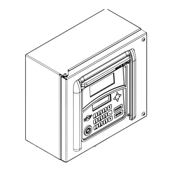
Page 27: Getting To Know Mc Box
- In SYSTEM mode, it displays prompts and data entries. - In DISPENSING mode, it displays the unit of measurement and user data. ① ② 27/124 27 / 68 This manual is the property of PIUSI S.p.A. Whole or partial reproduction of this manual is forbidden. -
Page 28: 13 3 Keypad
Installation, use and maintenance 13 3 KEYPAD The membrane keypad is used for entering data. It features: • 10 alphanumeric keys; • 8 special keys, as follows. STOP UP / DOWN stops the pump / quits any for scrolling through menus configuration menu. -
Page 29: Using Mc Box
(for example, printing out a report); such activities are represented by a broken line and a clock symbol. 29/124 29 / 68 This manual is the property of PIUSI S.p.A. Whole or partial reproduction of this manual is forbidden. -
Page 30: 14 3 Representations Of Key Presses
Installation, use and maintenance 14 3 REPRESENTATIONS OF KEY PRESSES (press and release immediately) SHORT KEY PRESS DOUBLE KEY PRESS (hold down the first key and then press and release the second one) TOUCH KEY (touch the electronic key to the reader) GENERIC ABCDEFGHIL REPRESENTATION OF... - Page 31 The TIMEOUT is not represented in the FLOW CHARTS. STOP KEY Pressing the STOP at any time to return to the start page “ENTER PIN CODE”/“TOUCH KEY” 31/124 31 / 68 This manual is the property of PIUSI S.p.A. Whole or partial reproduction of this manual is forbidden.
-
Page 32: Software Overview
Installation, use and maintenance 15 SOFTWARE OVERVIEW FOREWORD The AGILIS SELF SERVICE MANAGEMENT software functions are divided into SECTIONS. Each section contains a set of similar operations. Access to each section may be automatic, free or protected by a pin code. -
Page 33: 15 1 Boot
The system launches the ACCESS CONTROL section as soon as the boot section has completed. Access control is implemented in the following ways: 33/124 33 / 68 This manual is the property of PIUSI S.p.A. Whole or partial reproduction of this manual is forbidden. -
Page 34: Code Check
Installation, use and maintenance 15.2.1 CODE CHECK Press a NUMERIC key to start entering your PIN CODE: AGILIS checks that the PIN CODE is a valid (authorised) one, and whether it is assigned to a USER or the MANAGER. - INVALID CODE: AGILIS displays an unknown code message - VALID CODE: If the system recognises the code, depending on its type: - if the code is a USER PIN CODE, it launches the DISPENSING section;... -
Page 35: System Configuration
(using his code or key) to dispense fuel. DEFAULT value: 60 sec Values: 001 to 999 sec 35/124 35 / 68 This manual is the property of PIUSI S.p.A. Whole or partial reproduction of this manual is forbidden. - Page 36 Installation, use and maintenance FILLING TIME OUT This sets the maximum time for which dispensing can be interrupted. After having started to dispense fuel, - the user may interrupt it temporarily; - dispensing may be interrupted automatically by the nozzle. If dispensing is interrupted (with the pump on, but no fuel being dispensed) for longer than this setting, the pump is disabled and stops.
- Page 37 LINE DEL AY LINE DEL AY 1 00* 10 ms 1 23* 1 0 ms INPUT DELAY ENTER ENTER CANCEL 37/124 37 / 68 This manual is the property of PIUSI S.p.A. Whole or partial reproduction of this manual is forbidden.
- Page 38 Installation, use and maintenance CANCEL PC CONNECTED PCCONNECTED ENTER ENTER CANCEL CANCEL MEASUREMENT UNIT MEASUREMENT UNIT LITERS US G ALLONS ENTER ENTER CANCEL CANCEL DECIMAL DIGIT DECIMAL DIGIT ENTER ENTER CANCEL CANCEL NOZZLE TYPE NOZZLE TYPE NORMALLY CLOSED NORMALLY OPEN ENTER ENTER CANCEL...
- Page 39 DEFAULT value: Values: NO (do not send CR-LF) YES (send CR-LF) 39/124 39 / 68 This manual is the property of PIUSI S.p.A. Whole or partial reproduction of this manual is forbidden.
- Page 40 Installation, use and maintenance REMOTE PRINTER/LINE DELAY If the printer does not have enough memory to handle the print queue, you can change the line delay setting to make it possible for the printer to handle the queue without losing data N.B.: We advise leaving the default setting when making the first printouts.
- Page 41 (NEW MASTER KEY); 4. quit the CONFIGURATION menu (if you don not wish to change the MASTER KEY) by pressing CANCEL. 41/124 41 / 68 This manual is the property of PIUSI S.p.A. Whole or partial reproduction of this manual is forbidden.
-
Page 42: System Management
Installation, use and maintenance 17 SYSTEM MANAGEMENT Stand-by MODE FOREWORD MASTER KEY MASTER CODE The SYSTEM MANAGEMENT section allows the manager to complete routine AGILIS system management tasks. The SYSTEM MANAGEMENT section is divided into menus and submenus to enable quick access to the various options. - Page 43 “0000“. If on the other hand a given user has only a PIN CODE, it will be different form “0000“, and there will not be an asterisk in the USER KEY column. 43/124 43 / 68 This manual is the property of PIUSI S.p.A. Whole or partial reproduction of this manual is forbidden.
- Page 44 Installation, use and maintenance PRINT CODE - NO PRINT CODE - YES REPORT / CONFIGURATION Prints out the options selected in the configuration procedure, as follows: For the meanings of the various settings, refer to the SOFTWARE OVERVIEW chapter. 44 / 68 M0649...
- Page 45 LAST RESET TOTALS -> PRINT -> ONLY GENERAL TOTALS -> PRINT -> SINGLE -> USER TOTALS -> PRINT -> ALL 45/124 45 / 68 This manual is the property of PIUSI S.p.A. Whole or partial reproduction of this manual is forbidden.
-
Page 46: 172 User Menu
Installation, use and maintenance 17 2 USER MENU 46 / 68 M0649... - Page 47 - If you enter a USER NUMBER already belonging to another user, MC BOXac will refuse it and ask you to enter a new one. 47/124 47 / 68 This manual is the property of PIUSI S.p.A. Whole or partial reproduction of this manual is forbidden.
- Page 48 Installation, use and maintenance Once you have confirmed the automatic or manual option by pressing ENTER, the system will display all the new user’s data for a few seconds, and then return to the USER / ADD menu. N.B.: the system does not allow you to modify user data partially. If the data assigned to the new user are incorrect, you must: - cancel the new user (see par.
- Page 49 - USER NAME. USER - PIN CODE. NAME - KEY (if available). ABCDEFGHIL # 002 PIN 5678 USER CODE NUMBER 49/124 49 / 68 This manual is the property of PIUSI S.p.A. Whole or partial reproduction of this manual is forbidden.
- Page 50 Installation, use and maintenance NOTE: WHEN AUTHORISING A USER FOR THE FIRST TIME, ONLY THE “USER ADD?” MENU DISPLAYS. ONCE USERS HAVE BEEN AUTHORISED, THE SYSTEM WILL PROVIDE ACCESS TO ALL THE OTHER MENUS DESCRIBED IN THIS FLOW CHART. 50 / 68 M0649...
-
Page 51: 173 System Menu
The MEMORY RESET option is thus for use only when absolutely necessary, and should be preceded by printing out all the saved transactions before deleting them irreversibly. 51/124 51 / 68 This manual is the property of PIUSI S.p.A. Whole or partial reproduction of this manual is forbidden. - Page 52 Installation, use and maintenance SYSTEM / DATA / TIME Sets the system date and time, for logging with the transactions. N.B.: the system has a perpetual calendar which automatically changes the year and also accounts for leap years. The calendar does NOT change between summer and winter time. SYSTEM / LANGUAGE The Language Menu selects the interface language out of those available in the controller.
-
Page 53: 174 Check Key
2. The system displays the user data as shown if AAAA the key is recognised. # NNN PIN 1234 USER USER NUMBER PIN CODE 53/124 53 / 68 This manual is the property of PIUSI S.p.A. Whole or partial reproduction of this manual is forbidden. -
Page 54: 175 Calibration
Installation, use and maintenance 17 5 CALIBRATION FOREWORD Accesses a submenu with two options, for checking or modifying the CALIBRATION of the LITER COUNTER/PULSER. CALIBRATION VIEW Displays the current CALIBRATION FACTOR. The AGILIS MC BOXac must be calibrated for the liter counter in use. - Page 55 To do so, run a normal transaction with a user code (not the master code). We show the CALIBRATION flow chart below. 55/124 55 / 68 This manual is the property of PIUSI S.p.A. Whole or partial reproduction of this manual is forbidden.
-
Page 56: 176 Data Transfer
Installation, use and maintenance 17 6 DATA TRANSFER FOREWORD Transfers the transaction data from the AGILIS’s internal memory to the MASTER KEY. You can then use the key to transfer the data to a PC with a KEY READER, which must be running the AGILIS SELF SERVICE MANAGEMENT software. - Page 57 This message indicates that the MC BOX has no data to transfer and its memory is empty. We show the DATA TRANSFER flow chart below. 57/124 57 / 68 This manual is the property of PIUSI S.p.A. Whole or partial reproduction of this manual is forbidden.
-
Page 58: 177 Dispensing
Installation, use and maintenance 17 7 DISPENSING FOREWORD The DISPENSING section is used to dispense fuel. As soon a user is recognised, and after any optional inputs, the system enables dispensing. The NUMERIC displays goes from displaying the time to displaying the amount of fuel dispensed, displaying “000.0“... - Page 59 PRESET 1 2.5 L/GAL / STOP LITERS /US GALLONS PRESET 1 2.5 L/GAL WAIT PLEASE. . . PRINT REPORT 59/124 59 / 68 This manual is the property of PIUSI S.p.A. Whole or partial reproduction of this manual is forbidden.
-
Page 60: 1710 Dispensing - Message
Installation, use and maintenance 1710 DISPENSING - MESSAGE FOREWORD As soon as a USER enters his USER PIN CODE or touches his USER KEY to the unit’s reader, the system checks his authorisation in the ACCESS CONTROL section and displays one of the following messages: GOOD MORNING “USER”... -
Page 61: Maintenance
2. Open the MC BOXac AGILIS door to access the controller. 3. Loosen the screws of the metal rear panel to access the circuit boards compartment. 61/124 61 / 68 This manual is the property of PIUSI S.p.A. Whole or partial reproduction of this manual is forbidden. - Page 62 Installation, use and maintenance 4. Check the condition of the 3 fuses and replace them if necessary 800 mA T (time delay) power supply fuse on AC supply input. F2 20 A T (time delay) motor fuse. F3 800 mA T (time delay) power supply fuse on the AC/DC converter output. 5.
-
Page 63: 18 4 Firmware Update
Access the UPDATE FIRMWARE menu by pressing the key combination # + 2 when in the SYSTEM menu to enter the advanced options menu. DEFAULT value: Values: YES (enters FW UPDATE MODE). CHECK KEY 63/124 63 / 68 This manual is the property of PIUSI S.p.A. Whole or partial reproduction of this manual is forbidden. -
Page 64: Troubleshooting
Installation, use and maintenance 19 TROUBLESHOOTING PROBLEM CAUSES SOLUTIONS Lack of power due to: • Check connections The MC BOX does • Incorrect connections. • Set the circuit breaker to ON not switch on • Upstream circuit breaker set to OFF. •... - Page 65 Dip switch in position 1 Dip switch in position ON - - - - Manual Mode DOWN 65/124 65 / 68 This manual is the property of PIUSI S.p.A. Whole or partial reproduction of this manual is forbidden.
-
Page 66: Scrapping And Disposal
Installation, use and maintenance 20 SCRAPPING AND DISPOSAL FOREWORD In case the system should be demolished, its parts must be given to companies specialised in industrial waste disposal and recycling; in particular: PACKAGING DISPOSAL The package is made of biodegradable cardboard that can be consigned for sorted waste collection. DISPOSAL OF METAL PARTS The metal components, both painted and in stainless steel, are usually recycled by companies that are specialised in the metal-scrapping industry. -
Page 67: Replacement Parts Table
MC BOX EN (Translation of the original language) 21 REPLACEMENT PARTS TABLE 67/124 67 / 68 This manual is the property of PIUSI S.p.A. Whole or partial reproduction of this manual is forbidden. - Page 68 © PIUSI S.p.A. EN This document has been drawn up with great care concerning the accuracy of the data contained herein. However, PIUSI S.p.A. rejects all liability for any mistakes and omissions. Scarica il manuale nella tua lingua! EN Download the manual in your language! CS Stáhnout příručku ve vašem jazyce!
Need help?
Do you have a question about the MC BOX ac AGILIS and is the answer not in the manual?
Questions and answers