Table of Contents
Advertisement
Quick Links
Advertisement
Table of Contents

Subscribe to Our Youtube Channel
Summary of Contents for Templari KITA AIR R32
- Page 1 INSTALLATION INSTRUCTION A I R T O A I R Refrigerant gas...
-
Page 2: Table Of Contents
KITA AIR R32 Templari® external unit components diagram ......... 11 KITA AIR Plus R32 Templari® external unit components diagram ......12 KITA AIR R32 and AIR Plus R32 Templari® internal unit components diagram ..13 Transport ......................14 Mounting and installation..................14 6.1... - Page 3 Maintenance and cleaning ..................19 Finned coil cleaning ....................19 9.2 Condensate discharge cleaning ................20 Refrigerant circuit maintenance ................20 Electric connection ....................20 10.1 General information ..................... 20 10.1.1 T he customer/ installer has to: ................20 10.2 Operations of laying ..................... 20 10.3 External unit connection ..................20 10.4 Internal unit connection ..................20 10.5 Probes and remote controller ................
- Page 4 15.6 ON-OFF menu ....................... 35 15.7 SETPOINT menu ....................35 15.8 Clock/timetable menu ..................36 15.9 Input/Output menu ....................37 15.10 Alarms history menu .................... 37 15.11 Board change menu ....................37 15.12 Assistance menu ....................37 15.13 Menu overview ....................41 Alarms ........................42 16.1 Alarms resolution ....................44 16.2 Notifications ......................
-
Page 6: Introduction
Set of screwdrivers; This manual aims to give all the necessary information installation • Cutter; and proper operation of KITA - AIR Templari® heat pump, from • Scissors; its start-up and for all its life cycle. The document is divided •... -
Page 7: Read Carefully Before Use
This product contains fluorinated greenhouse gases covered by ATTENTION!! the Kyoto Protocol. Do not vent gases into the atmosphere. The use and the maintenance of the KITA - AIR Templari® heat pump, are subjected to the juridical ordinances of the Refrigerant type: R410A destination country. -
Page 8: Proper Use
This is why careful sizing of La pompa di calore Kita AIR R32 è omologata solo per l’uso the heat source and heating system is highly recommended. A previsto dal costruttore. -
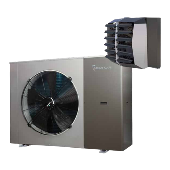
Page 9: Heat Pump Structure
• KITA AIR Templari® internal unit (aerothermal) for the diffusion of the air inside ambient; The KITA AIR Templari® heat pump is provided in 2 units and it’s • Remote control panel; consists of components which are indicated at page 4. - Page 10 1 – R-32 warning label 3 – refrigerant charge label R-32 Contiene gas fluorurati ad effetto serra inclusi nel protocollo di Kyoto This equipment contains fluorinated greenhouse gases Contains fluorinated greenhouse gases covered by the Kyoto Protocol covered by the Kyoto Protocol.
-
Page 11: Kita Air R32 Templari® External Unit Components Diagram
KITA AIR R32 Templari® external unit components diagram EVAPORATOR ECONOMIZER COMPRESSOR BALL VALVES FILTER CHECK VALVES LIQUID INDICATOR ELECTRONIC EXPANSION VALVE INVERTER 4-WAY VALVE LIQUID RECEIVER ELECTRIC BOARD The picture has the sole purpose of indicating the main internal components. The product may not be exactly as shown in the picture. -
Page 12: Kita Air Plus R32 Templari® External Unit Components Diagram
KITA AIR Plus R32 Templari® external unit components diagram TEMPLAR Via Pitago Tel. +39 049 EVAPORATOR ECONOMIZER COMPRESSOR BALL VALVES FILTER CHECK VALVES LIQUID INDICATOR ELECTRONIC EXPANSION VALVE INVERTER 4-WAY VALVE LIQUID RECEIVER ELECTRIC BOARD The picture has the sole purpose of indicating the main internal components. The product may not be exactly as shown in the picture. -
Page 13: Kita Air R32 And Air Plus R32 Templari® Internal Unit Components Diagram
KITA AIR R32 and AIR Plus R32 Templari® internal unit components diagram TEMPLARI Via Pitagora Tel. +39 049 DEFLECTOR EXCHANGER ELECTRIC PANEL SIDE COVER MAIN BOTTOM FRAME The picture has the sole purpose of indicating the main internal components. The product may not be exactly as shown in the picture. -
Page 14: Transport
In severe cases this may have as a 1791 consequence a failure inside. The transport to the final place of installation should be done on a pallelt. The heat pump KITA AIR Templari® can be transported using a forklift. 1791 KITA AIR R32 Kg. -
Page 15: Free Spaces For The Assembly
>1000 DESCR Respect the minimum distances mentioned above to ensure a sufficient air flow and facilitate maintenance works. TEMPLARI SRL - HEAT PUMP TECNOLOGY 1423 • If the product is installed in areas prone to heavy snowfalls, Via Pitagora, 20A - 35030 Rubano (PD) -
Page 16: External Unit Mounting
• Don’t install the product near wells of air discharge. • Prepare the laying of electrical cables. • In places where there are snowfalls, install the heat pump at least 25 cm from the ground to avoid clogging at the inlet and drain zone. -
Page 17: Correct Alignment
Correct alignment Put horizontally the heat pump KITA AIR Templari® so that the condensate can flow. The product must be installed with amortized feet, purchased separately. The amortized feet increase the height of the product, facilitating the flow of condensate and reducing vibrations. -
Page 18: Generalities And Choice Of The Installation Place
7.2 Generalities and choice of the installation place WARNING! Probe cable B2 • Install the unit in an internal environment. • The unit must not to be install near heat or steam sources. • Install the internal unit respecting the minimal distances from walls and obstacles for facilitate the assembly and maintenance operations. -
Page 19: Set Up For Installation And Refrigerant Pipelines Installation
Maintenance and cleaning 8.2 Set up for installation and refrigerant pipelines installation A regularly maintenance is necessary in particular for correct and efficient heat pump operations, so as to reduce damages The coolant pipes connections must be sealed to prevent and usury of the components. The user decides the maintenance leakage of the coolant and the consequent malfunctioning of the frequency. -
Page 20: Condensate Discharge Cleaning
9.2 Condensate discharge cleaning • Pass the power cables and the net control cable of the machine only trough proper holes. Please make sure that the condensate discharge pipe is in the 10.3 External unit connection correct position e without any obstruction to ensure a proper condensate flow from the finned coil fins. -
Page 21: I Nternal Unit Auxiliary Heater (Optional)
10.7 Power and signal cables characteristics EXTERNAL UNIT Power supply connection from 3P+N+T - 400 Vac - 50 Hz main electric panel AIR R32 12 kW 400 24A 3P+N+T 4x32A 5G4 4x32A Power supply cable from main SEE CHART AIR PLUS... -
Page 22: Terminal Box Wiring
11 Terminal box wiring 11.1 Mono-phase internal terminal box wiring 1PH TERMINAL BLOCK OF INDOOR UNIT N PE 1 TERMINAL BLOCK FOR ELECTRICAL PANEL OUTDOOR UNIT SENSORS CONNECTION 9 11 8 10 12 N PE N PE B2 - EXTERNAL POWER SUPPLY 11.2 3-phase internal terminal box wiring... - Page 23 Connector description: Subcooling RX-/TX- +Vdc Radiant probe RX+/TX+ Domestic probe +5 Vref Return probe Flow meter Vout Head compressor probe RX-/TX- Flow probe RX+/TX+ External temperature probe Drain probe Suction probe High pressure transducer +Vdc Low pressure transducer Summer-winter switch...
-
Page 24: Electronics (Upc)
12 Electronics (UPC) Power 24 Vdc Sensor power Analog inputs from B1 to B7 Port BMS Digital inputs from DI1 to DI7 Analog outputs from Y1 to Y4 Analog inputs from B8 to B12 Injection valve Digital inputs from DI8 to DI12... -
Page 25: Kita Air R32 And Air Plus R32 Electric Diagram
12.5 KITA AIR R32 and AIR PLUS R32 electric diagram... -
Page 26: Internal Unit Wiring Connection
12.6 Internal unit wiring connection Yellow/Green Yellow/Green Blue Blue Brown Yellow/Green Brown Blue N-Lok 3 Brown N-Lok 3 12.6.1 Fan N-Lok 3 Brown Brown Brown Brown Brown Yellow/Green Yellow/Green Blue Brown Blue Brown Yellow/Green Brown Blue N-Lok 6 Brown N-Lok 6 N-Lok 6 12.6.2 4-way valve and carter resistance wiring... -
Page 27: Kita Air R32 And Air Plus R32 Internal Unit Auxiliary Heating Element (Optional) Wiring Connection Diagram
12.7 KITA AIR R32 and AIR PLUS R32 internal unit auxiliary heating element (optional) wiring connection diagram This diagram is property of Templari srl. The total or partial reproduction to third parties, without our explicit consent, will be persecuted according to the law. -
Page 28: Commissioning
13 Commissioning management --˃ SERVICE PASSWORD --˃ Screen Gg02: set up “Speed Fan” in manual MAN and “Power required” at The plant commissioning should be realized by technical • Screen D08: verify that the value SH (overheating) is personnel that has received a complete training. -
Page 29: Connecting To The Kita Heat Pump
Each cable duct which ends on a sensor will then have at its inner 3 wirings: MODBUS cable: Templari HCC cable (similar Belden 2 MODBUS cables (one that comes inside plus one going out), plus 3105A 2x22AWG shielded) one power supply consists of 2 wires 2x1... -
Page 30: System Overview
14.3 System overview This is an example of how to set up the plant. +24V -24V 24out 24in Figure 2... - Page 31 K-Touch panel connected via BMS μPC G + - MODBUS ENDWIDERSTAND TERMINATOR 120Ω RESISTOR 120Ω K-Touch Panel connected via P-LAN as the only display MODBUS Connecting to ground...
-
Page 32: Exploded View: Plan Connection (7A) Or Bms Connection (7B)
14.4 Exploded view: PLan connection (7a) or BMS connection (7b) +24V -24V PLan CONNESSIONE connection PLan RX-/TX- RX+/TX+ CONNESSIONE BMS connection PLan PLan o BMS? BMS? μPC 220V Morse�o Terra Heat pump terminal quadro macchina board ground connection COM3 COM3 * For data lines with a total lenght of more than 10 meters, insert another 120 Ohm resistance into the last device. - Page 33 PGD connection Terminal block General terminal block B2-HCC -indoor for outdoor unit unit signal Outdoor unit terminal block Panoramic Power supply HCC - 24V power supply B2 signal Outdoor unit External power Internal power signal supply supply...
-
Page 34: Control Unit
15 Control unit 15.3 Control panel structure The terminal of the unit is connected serially through line P-LAN and can be installed in remote to control the unit. In the control software have been implemented all the settings necessary to... -
Page 35: Main Menu
15.6 ON-OFF menu The unit is in stand-by status: the antifreeze function is active (internal circulating pump activation and, if requested by very low external temperatures, compressor activation), but the heating/cooling regulation is not active On/Off Unit Unit Heat-pump... -
Page 36: Clock/Timetable Menu
Stop3 --/-- www.templari.com Mask B07: it manages the Automatic End Season. You have to set the daily medium external temperature over which Orologio you want the heating function is turned off; if present the Enable special days: NO domestic function stay active in any case. -
Page 37: Input/Output Menu
• Confirm with to enter the choice of the starting day of Mask D15: overheating of compressor drain and relevant the particular period. control type active. • Use the buttons to choose the starting day • SSH = Suction Super Heating •... - Page 38 Gc23: inverter status. and the previous higher, the boiler could start even if it Gc24: digital inputs isn’t necessary, for example if the machine stayed near Gc25: digital inputs the set (low proportional) for long time (high integral Gc26: digital inputs pushing), no reaching it.
- Page 39 • Manual: (default) the machine restarts only if the user resets the alarm manually. Mask Gfc37: defrost parameters. • Auto: the machine restart automatically Integration of the system during the • when the flow temperature is decreased to defrosting.: It enables the integration the value Set_alarm_overheat-Diff._Activat.
- Page 40 “Update rps” every “Update time” Mask Gg08: integration management. • if the current consumtion is included between • N06 Plant Integr.: auxiliary heater output (es. boiler). (Thr-Band) and Thr correction actions aren’t Mask Gg09: only in AIR version.
-
Page 41: Menu Overview
15.13 Menu overview... -
Page 42: Alarms
16 Alarms Alarm Visualized message Reset Delay Relay Action code ALA01 Probe B1 broken or disconnected Automatic 60 sec Stop the machine ALA02 Probe B2 broken or disconnected Automatic 60 sec If there is a geothermal modulating pump it is set at the maximum speed... - Page 43 Alarm Visualized message Reset Delay Relay Action code ALP01 Position: ID1 Flow switch geothermal circ. After 5 times per At the start: 15s (par. Stop the machine at maximum time reached water hour it becomes Hc15) at regime: 5s manual (par.
-
Page 44: Alarms Resolution
The letter preceding the number has the following meaning “AIN” Physic probes broken uPC “Pumps” Pumps flow switches, pumps thermic “Boh”Alarms blocking the Circuit, High-Low pressure.. “Quality”HACCP, Consumptions “Compressor” Thermic, envelope “Remote” Various alarms from digital inputs “Driver” Electronic valve “Serial probe”... - Page 45 www.templari.com...
- Page 46 www.templari.com...
- Page 47 www.templari.com...
- Page 48 Templari S.p.a. via C. Battisti, 169 35031 Abano Terme (PD) Italy Tel. +39 049 8597400 info@templari.com www.templari.com vers. 15/01/2024 - E...
Need help?
Do you have a question about the KITA AIR R32 and is the answer not in the manual?
Questions and answers