Table of Contents
Advertisement
Quick Links
INSTRUCTION MANUAL
PNP TRANSISTOR OUTPUT EXTENSION MODULE, 16 points
BEFORE USE ....
Thank you for choosing us. Before use, please check con-
tents of the package you received as outlined below.
If you have any problems or questions with the product,
please contact our sales office or representatives.
■ PACKAGE INCLUDES:
Transistor output extension module ..................................(1)
■ MODEL NO.
Confirm Model No. marking on the product to be exactly
what you ordered.
■ INSTRUCTION MANUAL
This manual describes necessary points of caution when
you use this product, including installation, connection and
basic maintenance procedures.
POINTS OF CAUTION
■ POWER INPUT RATING & OPERATIONAL RANGE
• Locate the power input rating marked on the product and
confirm its operational range as indicated below:
24V AC rating: 24V ±10%, 50/60 Hz, approx. 30mA
24V DC rating: 24V ±10%, approx. 20mA
■ GENERAL PRECAUTIONS
• Before you remove the unit or mount it, turn off the power
supply and output signal for safety.
■ ENVIRONMENT
• Indoor use.
• When heavy dust or metal particles are present in the
air, install the unit inside proper housing with sufficient
ventilation.
• Do not install the unit where it is subjected to continuous
vibration. Do not subject the unit to physical impact.
• Environmental temperature must be within -10 to +55°C
(14 to 131°F) with relative humidity within 30 to 90% RH
in order to ensure adequate life span and operation.
■ WIRING
• Do not install cables close to noise sources (relay drive
cable, high frequency line, etc.).
• Do not bind these cables together with those in which
noises are present. Do not install them in the same duct.
■ FUNCTIONAL BLOCK SETTING
• Functional blocks regarding the extension module are set
by the basic module. Refer to the instruction manual for
the basic module for detailed information.
■ AND ....
• The unit is designed to function as soon as power is sup-
plied, however, a warm up for 10 minutes is required for
satisfying complete performance described in the data
sheet.
MG CO., LTD. www.mgco.jp
5-2-55 Minamitsumori, Nishinari-ku, Osaka 557-0063 JAPAN
(L
W
)
ON
ORKS
MODEL
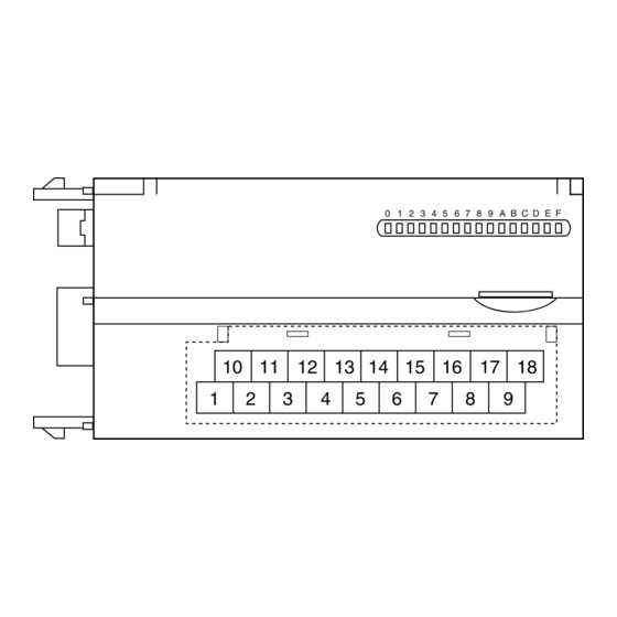
COMPONENT IDENTIFICATION
Discrete Output Status Indicator LED
10 11 12 13
1
2
■ DISCRETE OUTPUT STATUS INDICATOR LED
Used to show discrete output signal status.
ON
: LED ON
OFF
: LED OFF
■ OUTPUT TERMINAL ASSIGNMENT
10
11
12
13
+24V
Y1
Y3
Y5
1
2
3
4
5
0V
Y0
Y2
Y4
NO.
ID
FUNCTION
1
0V
0V
2
Y0
Output 0
3
Y2
Output 2
4
Y4
Output 4
5
Y6
Output 6
6
Y8
Output 8
7
YA
Output 10
8
YC
Output 12
9
YE
Output 14
R7L-EC16B
0 1 2 3 4 5 6 7 8 9 A B C D E F
14
15 16 17 18
3
4
5
6
7
8
9
Output Terminals
14
15
16
17
18
Y7
Y9
YB
YD
YF
6
7
8
9
Y6
Y8
YA
YC
YE
NO.
ID
FUNCTION
10
+24V
24V DC (common)
11
Y1
Output 1
12
Y3
Output 3
13
Y5
Output 5
14
Y7
Output 7
15
Y9
Output 9
16
YB
Output 11
17
YD
Output 13
18
YF
Output 15
EM-7804-K Rev.2 P. 1 / 3
Advertisement
Table of Contents

Related Manuals for MG R7L-EC16B


Summary of Contents for MG R7L-EC16B
- Page 1 • The unit is designed to function as soon as power is sup- plied, however, a warm up for 10 minutes is required for satisfying complete performance described in the data sheet. EM-7804-K Rev.2 P. 1 / 3 MG CO., LTD. www.mgco.jp 5-2-55 Minamitsumori, Nishinari-ku, Osaka 557-0063 JAPAN...
- Page 2 (.45) DIN RAIL 35mm wide 10 11 12 13 15 16 17 18 30 (1.18) [5 (.20)] 6 (.24) 18–M3 SCREW TERMINALS for OUTPUT EM-7804-K Rev.2 P. 2 / 3 MG CO., LTD. www.mgco.jp 5-2-55 Minamitsumori, Nishinari-ku, Osaka 557-0063 JAPAN...
- Page 3 (AWG 22 to 16) Recommended manufacturer: Japan Solderless Terminal MFG. Co., Ltd, Nichifu Co., Ltd 3.3 (.13) max mm (inch) Output Connection Example – +24V EM-7804-K Rev.2 P. 3 / 3 MG CO., LTD. www.mgco.jp 5-2-55 Minamitsumori, Nishinari-ku, Osaka 557-0063 JAPAN...
Need help?
Do you have a question about the R7L-EC16B and is the answer not in the manual?
Questions and answers