Advertisement
Quick Links
INSTRUCTION MANUAL
DISCRETE INPUT EXTENSION MODULE, 8 points
(MECHATROLINK-I / -II)
BEFORE USE ....
Thank you for choosing us. Before use, please check con-
tents of the package you received as outlined below.
If you have any problems or questions with the product,
please contact our sales office or representatives.
■ PACKAGE INCLUDES:
Discrete input extension module ........................................(1)
■ MODEL NO.
Confirm that the model number described on the product is
exactly what you ordered.
■ INSTRUCTION MANUAL
This manual describes necessary points of caution when
you use this product, including installation,
POINTS OF CAUTION
■ POWER INPUT RATING & OPERATIONAL RANGE
• Locate the power input rating marked on the product and
confirm its operational range as indicated below:
24V DC rating: 24V ±10%, approx. 10mA
■ GENERAL PRECAUTIONS
• Before you remove the unit or mount it, turn off the power
supply and input signal for safety.
■ ENVIRONMENT
• Indoor use
• When heavy dust or metal particles are present in the
air, install the unit inside proper housing with sufficient
ventilation.
• Do not install the unit where it is subjected to continuous
vibration. Do not subject the unit to physical impact.
• Environmental temperature must be within 0 to 55°C (32
to 131°F) with relative humidity within 30 to 90% RH in
order to ensure adequate life span and operation.
■ WIRING
• Do not install cables close to noise sources (relay drive
cable, high frequency line, etc.).
• Do not bind these cables together with those in which
noises are present. Do not install them in the same duct.
■ AND ....
• The unit is designed to function as soon as power is sup-
plied, however, a warm up for 10 minutes is required for
satisfying complete performance described in the data
sheet.
MG CO., LTD. www.mgco.jp
5-2-55 Minamitsumori, Nishinari-ku, Osaka 557-0063 JAPAN
MODEL
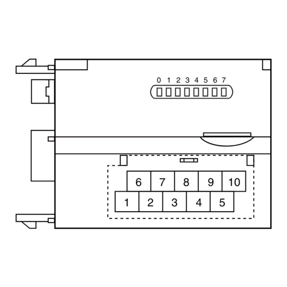
COMPONENT IDENTIFICATION
Discrete Input Status Indicator LED
■ DISCRETE INPUT STATUS INDICATOR LED
Discrete input modules including those for extensions have
LED indicators showing input signal status.
Contact ON : LED ON
Contact OFF : LED OFF
■ INPUT TERMINAL ASSIGNMENT
6
7
NC
X1
1
2
COM
X0
NO.
ID
FUNCTION
1
COM
Common
2
X0
Input 0
3
X2
Input 2
4
X4
Input 4
5
X6
Input 6
CONNECTING THE EXTENSION MODULE
1) Remove the extension connector cover located at the side
of the basic module.
2) Connect the extension module.
3) Mount the combined module on a DIN rail.
R7ML-EA8
R7ML-EA8
0
1
2
3
4
5
6
7
6
7
8
9
10
1
2
3
4
5
Input Terminals
8
9
10
X3
X5
X7
3
4
5
X2
X4
X6
NO.
ID
FUNTION
6
NC
No Connection
7
X1
Input 1
8
X3
Input 3
9
X5
Input 5
10
X7
Input 7
EM-7805-N Rev.4 P. 1 / 3
Advertisement

Related Manuals for MG R7ML-EA8


Summary of Contents for MG R7ML-EA8
- Page 1 • The unit is designed to function as soon as power is sup- plied, however, a warm up for 10 minutes is required for satisfying complete performance described in the data sheet. EM-7805-N Rev.4 P. 1 / 3 MG CO., LTD. www.mgco.jp 5-2-55 Minamitsumori, Nishinari-ku, Osaka 557-0063 JAPAN...
- Page 2 Recommended manufacturer: Japan Solderless Terminal MFG. Co., Ltd, Nichifu Co., Ltd 3.3 (.13) max mm (inch) Input Connection Examples PNP Connection NPN Connection – – + EM-7805-N Rev.4 P. 2 / 3 MG CO., LTD. www.mgco.jp 5-2-55 Minamitsumori, Nishinari-ku, Osaka 557-0063 JAPAN...
- Page 3 R7ML-EA8 I/O DATA DESCRIPTION ■ DISCRETE INPUT Input 0 Input 1 Input 2 Input 3 Input 7 Unused Unused 0:OFF 1:ON EM-7805-N Rev.4 P. 3 / 3 MG CO., LTD. www.mgco.jp 5-2-55 Minamitsumori, Nishinari-ku, Osaka 557-0063 JAPAN...
Need help?
Do you have a question about the R7ML-EA8 and is the answer not in the manual?
Questions and answers