
Related Manuals for Circutor CBS-2000AB

Summary of Contents for Circutor CBS-2000AB
- Page 1 Multi-channel earth leakage current monitor CBS-2000AB, CBS-1600A INSTRUCTION MANUAL (M340B01-03-22A)
- Page 2 CBS-2000AB, CBS-1600A Instruction Manual...
-
Page 3: Safety Precautions
CIRCUTOR S�A�U� reserves the right to make modifications to the device or the unit specifications set out in this instruction manual without prior notice. CIRCUTOR S�A�U� on its web site, supplies its customers with the latest versions of the device specifi- cations and the most updated manuals. -
Page 4: Table Of Contents
4�3�- KEYBOARD FUNCTIONS �����������������������������������������������������������������������������������������������������������������������������������������22 4�4�- RELAYS ������������������������������������������������������������������������������������������������������������������������������������������������������������������22 4�5�- DIGITAL INPUT �������������������������������������������������������������������������������������������������������������������������������������������������������22 5�- DISPLAY �������������������������������������������������������������������������������������������������������������������������������������������������������������������������23 5�1�- PROBLEMS OR CHANGES IN THE INSTALLATION (Model CBS-2000AB) ��������������������������������������������������������������23 5�2�- DISPLAY SCREENS �������������������������������������������������������������������������������������������������������������������������������������������������24 5�3�- TRIP DISPLAY SCREENS �����������������������������������������������������������������������������������������������������������������������������������������25 5�3�1�- TYPE B CHANNELS ������������������������������������������������������������������������������������������������������������������������������������������26 5�3�2�- TYPE A CHANNELS ������������������������������������������������������������������������������������������������������������������������������������������26 5�3�3�- EXTERNAL TRIP, COMMUNICATIONS TRIP�������������������������������������������������������������������������������������������������������... - Page 5 7�3�5�- TRIP BY TEST OR COMMUNICATIONS OF TYPE A CHANNELS �������������������������������������������������������������������������48 7�3�6�- EVENTS ������������������������������������������������������������������������������������������������������������������������������������������������������������49 7�3�7�- DEVICE CONFIGURATION PARAMETERS �������������������������������������������������������������������������������������������������������� 50 8�- TECHNICAL FEATURES ��������������������������������������������������������������������������������������������������������������������������������������������������53 8�1�- CBS-1600A ������������������������������������������������������������������������������������������������������������������������������������������������������������53 8�2�- CBS-2000AB ���������������������������������������������������������������������������������������������������������������������������������������������������������55 8�3�- WGB �����������������������������������������������������������������������������������������������������������������������������������������������������������������������57 8�4�- WGC �����������������������������������������������������������������������������������������������������������������������������������������������������������������������59 9�- MAINTENANCE AND TECHNICAL SERVICE �������������������������������������������������������������������������������������������������������������������63 10�- GUARANTEE ����������������������������������������������������������������������������������������������������������������������������������������������������������������63 11�- EU DECLARATION OF CONFORMITY ����������������������������������������������������������������������������������������������������������������������������64...
-
Page 6: Revision Log
CBS-2000AB, CBS-1600A REVISION LOG Table 1: Revision log� Date Revision Description 03/22 M340B01-03-22A First Version SYMBOLS Table 2: Symbols� Symbol Description In accordance with the relevant European directive. Device covered by European Directive 2012/19/EC. At the end of its useful life, do not discard of the device in a household refuse bin. -
Page 7: 1�- Verification Upon Reception
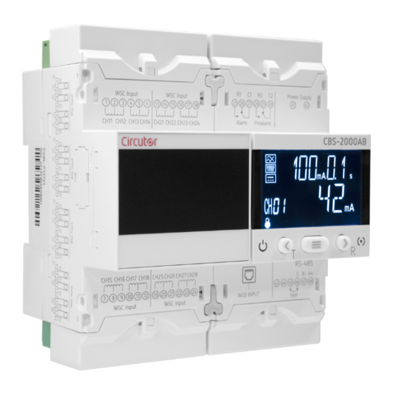
CIRCUTOR's after-sales service. 2 - PRODUCT DESCRIPTION The CBS-2000AB is a hybrid earth leakage current monitoring device that can be used to connect up to 16 type-A channels via transformers in the WGC range, and 4 type-B channels using transformers in the WGB range. - Page 8 - 6 LEDs providing information about the transformer's status. - 2 RJ45 connection and power supply ports. The WGC is a range of electronic, type A earth leakage protection and monitoring transformers (IEC 60044-1). CIRCUTOR offers 14 models, depending on the size of the transformer. Instruction Manual...
-
Page 9: 3�- Installation Of The Device
The CBS-2000AB / CBS-1600A device must be installed by authorised and qualified staff. The power supply plug must be disconnected and measurement systems switched off before handling, altering the connections or replacing the device. -
Page 10: 3�2�- Installation
CBS-2000AB, CBS-1600A 3�2�- INSTALLATION When the device is on, its terminals, opening covers or removing elements may ex- pose the user to parts that are hazardous to touch. Do not use the device until it is fully installed. The device must be installed inside a medium or low voltage electric panel or enclosure, with DIN rail mounting (IEC 60715). -
Page 11: 3�3�2� Cbs-2000Ab
3�3�2� CBS-2000AB Central Módulo/Module Módulo/Module Central Figure 2: Terminals of the CBS-2000AB: Upper - Lower� Table 5: List of terminals on the CBS-2000AB (Central)� Device terminals: Central A1: A1, Power supply 30: C2, Common prealarm relay A2: A2, Power supply... -
Page 12: 3�4�- Wgb And Wgc Transformers
CBS-2000AB, CBS-1600A Table 6: List of terminals on the CBS-2000AB (Module)� Device terminals: Module 1: CH11, 1S1 WGC input Channel 1.1 13: CH21, 1S1 WGC input Channel 2.1 2: CH11 - CH12, 1S2 WGC input Channel 1.1 and 1.2 14: CH21 - CH22, 1S2 WGC input Channel 2.1 and 2.2 3: CH12, 1S1 WGC input Channel 1.2... -
Page 13: 3�4�2� Din Rail Installation Of Wgb Transformers
CBS-2000AB, CBS-1600A Figure 4: Position of the clamping clips� 3�4�2� DIN RAIL INSTALLATION OF WGB TRANSFORMERS For installation on a DIN rail, a support bracket is provided with the device, see Figure 5 Figure 5: Support bracket� The steps to ensure proper installation are: 1�-... - Page 14 CBS-2000AB, CBS-1600A Figure 6: Installation on a DIN rail� Note: To remove the bracket from the DIN rail, use a screwdriver to pry it off, Figure 7 Figure 7: To remove the bracket use a screwdriver� Instruction Manual...
-
Page 15: 3�4�3� Din Rail Installation Of Wgc Transformers
CBS-2000AB, CBS-1600A 3�4�3� DIN RAIL INSTALLATION OF WGC TRANSFORMERS For installation on a DIN rail, two support brackets are provided with the device, see Figure 8 Figure 8: WGC support brackets� The steps to ensure proper installation are: 1�- Install the brackets in the WGC, Step 1 in Figure 9 2�- Install the WGC on the DIN rail, Step 2 in... -
Page 16: 3�4�4� Transformer Terminals
3�4�4� TRANSFORMER TERMINALS Figure 10: WGB terminals� Table 7: List of WGB terminals Device terminals 1, 2 Connection terminals to the CBS-2000AB and to the rest of WGB transformers. 3�4�5� TRANSFORMER LEDs WGB transformers have 6 indicating LEDs. Power Supply Channel TRIP Figure 11: WGB transformer LEDs�... -
Page 17: 3�5�- Connection Diagrams
CBS-2000AB, CBS-1600A 3�5�- CONNECTION DIAGRAMS 3�5�1� CBS-1600A CH11 Alimentación Auxiliar CH12 CH13 CH14 CH21 CH22 CH23 CH24 Power Supply 1S1 1S2 1S1 1S1 1S2 1S1 1S1 1S2 1S1 1S1 1S2 1S1 45 46 1S1 1S2 1S1 1S1 1S2 1S1 1S1 1S2 1S1 1S1 1S2 1S1... -
Page 18: 3�5�2� Cbs-2000Ab
1S1 1S2 1S1 1S1 1S2 1S1 1S1 1S2 1S1 1S1 1S2 1S1 WGB3 WGB2 45 46 1S1 1S2 1S1 1S1 1S2 1S1 1S1 1S2 1S1 1S1 1S2 1S1 CH15 CH16 CH17 CH25CH26 CH27CH28 CH18 TRIP WGB1 Figure 13: CBS-2000AB connection diagram� Instruction Manual... -
Page 19: 3�6�- Installation Connections
WGC (2-wire connection) or WGB (connection via RJ-45 cable) transform- ers. For each of the type-B channels to be monitored, connect the WGB transformer to the CBS-2000AB or to the next transformer in the installation using the RJ-45 cable,... -
Page 20: 4�- Operation
CBS-2000AB, CBS-1600A 4.- OPERATION 4�1�- LED INDICATORS The CBS-2000AB / CBS-1600A device has 2 LEDs: - CPU, white color, indicates that the device is on. - ALARM, Table 9: ALARM LED� Description Flashing red: Indicates that a prealarm has been generated. -
Page 21: 4�2�- Display
Data area Unit and status areas Figure 16: CBS-2000AB / CBS-1600A display areas� The data area, which displays all the values measured by the device. The unit and device status area, which displays the different statuses, units and device infor-... -
Page 22: 4�3�- Keyboard Functions
Access to direct settings, to the setup, event or lock menu, depending on the screen being displayed. 4�4�- RELAYS The CBS-2000AB / CBS-1600A has 2 output relays, an R1 alarm relay and an R2 prealarm relay (cen- tral terminals 25... 30 in Figure 1 Figure 2 to configure the parameters of the trip relay and “5.5 - DIRECT SETTINGS”... -
Page 23: 5�- Display
5�1�- PROBLEMS OR CHANGES IN THE INSTALLATION (Model CBS-2000AB) If the CBS-2000AB detects a problem in the installation at the end of boot up, the screens will be lit in yellow and one of the following screens will be displayed: The installation has changed and the device can’t find the WGB. -
Page 24: 5�2�- Display Screens
Leakage current instantaneous Figure 18: Display screen� Use the keys to browse through the different screens: Note: Screen visible on the CBS-2000AB model. Channel 1 (Type B Channel): Trip current (mA) Trip delay Instantaneous total leakage current (AC + DC) (mA) ... -
Page 25: 5�3�- Trip Display Screens
Note: If no key is pressed for 1 minute, the device skips to the Chan- nel 1 display screen. Screen with information on the device version. Press the key to see the CBS-2000AB/CBS-1600A version. Access the lock menu by pressing the key (See “5.7 - LOCK”... -
Page 26: 5�3�1�- Type B Channels
CBS-2000AB, CBS-1600A 5�3�1�- TYPE B CHANNELS Note: Screens visible on the CBS-2000AB model. Trip current (mA) Trip delay Total leakage current (AC + DC) that tripped the relay (mA) Trip current (mA) Trip delay AC leakage current that tripped the relay (mA) -
Page 27: 5�3�3�- External Trip, Communications Trip
CBS-2000AB, CBS-1600A 5�3�3�- EXTERNAL TRIP, COMMUNICATIONS TRIP If a trip has been generated using the TRIP input or via communications, the following screens are shown: If an external trip has been generated using the digital TRIP input on the device. -
Page 28: 5�5 �- Direct Settings
CBS-2000AB, CBS-1600A 5�5 �- DIRECT SETTINGS From the channel’s display screens, we can configure the trip current and delay for each of the relays. To do so, press the key while the screen for the channel you want to adjust is being displayed. -
Page 29: 5�6�- Event Menu
To enter the event menu, we must display the Events screen and press the key The device displays the last 20 events generated. The CBS-2000AB / CBS-1600A saves 4 different types of events: TRIP, trip of a channel’s relay. ALA, prealarm activated. - Page 30 CBS-2000AB, CBS-1600A Event 1 of channel 1: Event 1 of channel 1: Event 1 of channel 1: Prealarm Prealarm Prealarm Year Time Month and Day Event 5 of channel 5: Test Event 5 of channel 5: Test Event 5 of channel 5: Test...
-
Page 31: 5�7�- Lock
CBS-2000AB, CBS-1600A 5�7�- LOCK To enter the lock menu, we must display the Lock screen and press the key Figure 22: Lock menu� The lock configuration screen is shown. If the device locks: - The direct settings screens are locked ( ) and the values cannot be modi- “5.5 - DIRECT SETTINGS”... -
Page 32: 6�- Configuration
To enter the setup menu, we must display the Setup screen and press the key for > 3s. Note: If the device locks up, , the menu cannot be accessed. The CBS-2000AB/CBS-1600A organizes the device’s configuration into 6 menus, Figure 23 RS-485 communications > 3 s. -
Page 33: 6�1�- Rs-485 Communications
CBS-2000AB, CBS-1600A 6�1�- RS-485 COMMUNICATIONS shows the initial screen of the RS-485 communications menu. Press the key , to access Figure 24 the menu. Figure 24: Communications menu� 6�1�1�- BAUD RATE This screen is used to set up the baud rate of the RS-485 communications. -
Page 34: 6�1�3�- Data Format
CBS-2000AB, CBS-1600A Configuration values Table 16:Configuration values: Peripheral Number� Peripheral Number Minimum value Maximum value Press the key for > 3s to validate the data and exit edit mode. To skip to the next programming point, press the key 6�1�3�- DATA FORMAT... -
Page 35: 6�2�- Clock Setup Menu
CBS-2000AB, CBS-1600A 6�2�- CLOCK SETUP MENU shows the initial screen of the clock setup menu, press the key , to access the menu. Figure 25 Figure 25: Clock setup menu� shows the year setup screen. Figure 26 Figure 26: Clock setup: Year�... -
Page 36: 6�3�-Global Settings
CBS-2000AB, CBS-1600A Press the key to increase the hour value, and the key to decrease it. Press the key to confirm the value and configure the minutes, pressing the keys Press the key key for 3 seconds to finish setup, the screen in is displayed. -
Page 37: 6�3�2�- Delay
CBS-2000AB, CBS-1600A Press the key for > 3s to validate the data and exit the programming. 6�3�2�- DELAY The screen is used to adjust the relay trip delay for all the type A channels (Channels 1�1 ��� 2�8). Use the key to skip through the different options. -
Page 38: 6�4�1�- Prealarm Channel
CBS-2000AB, CBS-1600A 6�4�1�- PREALARM CHANNEL This screen is used to select the channel whose prealarm values are to be configured. Press the key to enter edit mode, the programming value flashes. Use the keys to modify the value. Configuration values Table 20:Configuration values: Prealarm channel�... -
Page 39: 6�4�3�- Operation Of Channel X's Prealarm
Press the key for > 3s to exit the menu. 6�5�- CHANNELS Note: Menu visible on the CBS-2000AB model. shows the initial screen of the switching menu for the type B channels (Channels 1��� 4). Figure 33 Press the key , to access the menu. -
Page 40: 6�5�1�- Channel Switching
CBS-2000AB, CBS-1600A 6�5�1�- CHANNEL SWITCHING In this screen we can switch the type B channels detected by the CBS-2000AB, i.e., we can configure that channel 1 detected by the CBS-2000AB becomes channel 2. Only one channel can be switched at a time, each time we enter the menu. - Page 41 CBS-2000AB, CBS-1600A Configuration values Table 23:Configuration values: Save installation� Save installation YES, saves the new installation. Possible values NO, does not save the new installation. Press the key for > 3s to validate the data and exit the programming.
-
Page 42: 7�- Rs-485 Communications
CBS-2000AB, CBS-1600A 7.- RS-485 COMMUNICATIONS The CBS-2000AB / CBS-1600A has an RS-485 communications port. The device is equipped with the MODBUS RTU communication protocol as standard. 7�1�- CONNECTIONS The RS-485 cable must be wired using twisted pair cable with mesh shield (minimum 3 wires), with a maximum distance of 1200 meters between the CBS-2000AB / CBS-1600A and the master unit. -
Page 43: 7�3�- Modbus Commands
7�3�1�-DEVICE AND INSTALLATION PARAMETERS Function 0x02 is used for these parameters. Functions 0x01 and 0x05 are used for the parameter Save the new installation. Table 24: Modbus Memory Map: Device - Installation (Table 1)� CBS-2000AB / CBS-1600A - INSTALLATION Parameter Format Address... -
Page 44: 7�3�2�- Parameters Of The Type B Channels
More WGBs than the installation can accept have been detected. There is no WGB registered in the installation. Possible statuses of CBS-2000AB / CBS-1600A, Table 27 Table 27: Status of CBS-2000AB / CBS-1600A� Possible statuses CBS-2000AB/CBS-1600A Value Description Device started. - Page 45 CBS-2000AB, CBS-1600A Table 28 (Continuation): Modbus Memory Map: Parameters of the type B channels� Address Units Parameter Format Format Channel 1 Channel 2 Channel 3 Channel 4 AC trip current Unit [16] 107C 1144 120C DC trip current Unit [16]...
-
Page 46: 7�3�3�- Parameters Of The Type A Channels
CBS-2000AB, CBS-1600A 7�3�3�- PARAMETERS OF THE TYPE A CHANNELS Function 0x04: register readout, is used for these parameters. Table 31: Modbus Memory Map: WGC module parameters� Parameter Format Address WGC module model String 1770 - 1771 Serial No of the WGC String 1772...1778... - Page 47 CBS-2000AB, CBS-1600A Tabla 34 (Continued): Modbus Memory Map: Parameters of the type A channels� Parameter Address Value Format Channel 1�1 Channel 1�2 Channel 1�3 Channel 1�4 Channel tripped bool 03EA 03F3 03FC 0405 Channel tripped due to leakage bool 03EB...
-
Page 48: 7�3�4�- Trip By Test Or Communications Of Type B Channels
0477 1: Detected 7�3�4�- TRIP BY TEST OR COMMUNICATIONS OF TYPE B CHANNELS Note: Parameters available on the CBS-2000AB model. Function 0x01 and 0x05 is used for these parameters. Table 35: Modbus Memory Map: Configuration of the trip and prealarm�... -
Page 49: 7�3�6�- Events
CBS-2000AB, CBS-1600A Table 36 (Continued): Modbus Memory Map: Configuration of the trip and prealarm� Type A channels: Configuration of the Trip and Prealarm Channel Channel Channel Channel Default Parameter Format Valid data range 1�5 1�6 1�7 1�8 value FF00: Activate the TEST... -
Page 50: 7�3�7�- Device Configuration Parameters
Function 0x10: Writing multiple registers. 7�3�7�1�- Type B channels: Configuration of the trip and prealarm Note: Parameters available on the CBS-2000AB model. Table 38: Modbus Memory Map: Configuration of the trip and prealarm� Type B channels: Configuration of the Trip and Prealarm... - Page 51 CBS-2000AB, CBS-1600A Table 40: Modbus Memory Map: Trip current table� Type B channels: Trip current Address Parameter Format Function Value Channel 1 Channel 2 Channel 3 Channel 4 30 mA Value 1 Unit [16] 0x04 1014 10DC 11A4 126C 100 mA...
- Page 52 Data format Unit [16] 36B3 3: 8N2, 4: 8E2, 5: 802 7�3�7�4�- Type B channels: Channel switching Note: Parameters available on the CBS-2000AB model. Table 43: Modbus Memory Map: Channel switching� Type B channels: Channel switching Configuration parameters Format Address...
-
Page 53: 8�- Technical Features
CBS-2000AB, CBS-1600A 8.- TECHNICAL FEATURES 8�1�- CBS-1600A AC Power supply Rated voltage 230 V ~ ± 15% Frequency 50 ... 60 Hz Consumption 10 VA Installation category CAT III 300V Current measurement circuit Channel Type A Input sensor WGC - WGS Frequency 50 ... - Page 54 Dimensions Figura 36 (mm) Weight 364 g. Enclosure Self-extinguishing V0 plastic Fixing DIN rail Standars Electrical accessories - Residual current monitors (RCMs) - Part 1: RCMs for household and IEC 62020-1 similar uses Figure 36: Dimensions CBS-1600A, CBS-2000AB� Instruction Manual...
-
Page 55: 8�2�- Cbs-2000Ab
CBS-2000AB, CBS-1600A 8�2�- CBS-2000AB AC Power supply Rated voltage 230 V ~ ± 15% Frequency 50 ... 60 Hz Consumption 15 VA Installation category CAT III 300V Current measurement circuit Channel Type A Input sensor WGC - WGS Frequency 50 ... 60 Hz... - Page 56 IK08 Pollution degree Indoor Mechanical features Terminals: A1, A2, 1 ... 48 2.5 mm ≤ 0.4 Nm, M2.5 Flat Cable from WGB to CBS-2000AB Connector RJ-45 standard Cross section 4 x 2 x AWG24/7 Temperature range -20ºC ... +70ºC Dimensions...
-
Page 57: 8�3�- Wgb
Ø 110.5 mm Weight 235 g. 355 g. 555 g. 710 g. Enclosure Self-extinguishing V0 plastic Cable from WGB to CBS-2000AB Connector RJ-45 standard Cross section 4 x 2 x AWG24/7 Temperature range - 20 ºC ... +70 ºC Length 1.5 m... - Page 58 CBS-2000AB, CBS-1600A WGB-xxx Ø6.5 Figure 37: WGB dimensions� Figure 38: WGB dimensions� WGB dimensions WGB-35 61.5 35.5 44.5 WGB-55 98.5 55.5 52.5 81.5 WGB-80 123.5 81.5 80.5 101.5 WGB-110 153.5 96.5 110.5 Instruction Manual...
-
Page 59: 8�4�- Wgc
0.1 ... 2.5 mm (Rigid) S1, S2 27 ... 12 AWG (flexible) Cable from WGC to CBS-2000AB/CBS-1600A Wire section wiring ≥ 1 mm 0 ... 1 m Twisted and shielded wire section wiring ≥ 1 mm 0 ... 10 m... - Page 60 CBS-2000AB, CBS-1600A Models Weight Useful section WGS-20 76 g. Ø 20 mm WGC-20-SC 81 g. WGC-25 80 g. Ø 25 mm WGS-30 95 g. Ø 30 mm WGC-30-SC 100 g. WGC-35 120 g. Ø 35 mm WGC-55 160 g. Ø 55 mm WGC-80 300 g.
- Page 61 CBS-2000AB, CBS-1600A Figure 42:Dimensions WGC-55, WGC-80, WGC-110, WGC-140 and WGC-180� Dimensions WGC-55, WGC-80, WGC-110, WGC-140, WGC-180 WGC-55 WGC-80 124.5 WGC-110 84.5 WGC-140 WGC-180 Figure 43: Dimensions WGC-220x105, WGC-350x150 and WGC-500x200� Figure 44: Dimensions WGC-220x105, WGC-350x150 and WGC-500x200� Dimensions WGC-220x105, WGC-350x150, WGC-500x200 WGC-220x105 50.2...
- Page 62 CBS-2000AB, CBS-1600A 24,4 ±0,2 Ø30 Figure 46: Dimensions WGC-30-SC� Instruction Manual...
-
Page 63: 9�- Maintenance And Technical Service
CBS-2000AB, CBS-1600A 9.- MAINTENANCE AND TECHNICAL SERVICE In the case of any query in relation to device operation or malfunction, please contact the CIRCUTOR S�A�U� Technical Support Service. Technical Assistance Service Vial Sant Jordi, s/n, 08232 - Viladecavalls (Barcelona) Tel: 902 449 459 (Spain) / +34 937 452 919 (outside of Spain) email: sat@circutor.com... -
Page 64: 11�- Eu Declaration Of Conformity
CBS-2000AB, CBS-1600A 11.- EU DECLARATION OF CONFORMITY Instruction Manual... - Page 65 CBS-2000AB, CBS-1600A Instruction Manual...
- Page 66 CBS-2000AB, CBS-1600A Instruction Manual...
-
Page 67: Annex A.- Direct Settings
CBS-2000AB, CBS-1600A ANNEX A.- DIRECT SETTINGS Trip current Channels 1...4: > 3 s. > < . . Channels 1.1...2.8: > < . . . . Delay and relay curve Channels 1...4: 0.... -
Page 68: Annex B.- Configuration Menu
CBS-2000AB, CBS-1600A ANNEX B.- CONFIGURATION MENU . . Baud rate > < . . . . < > Peripheral < > > 3 s. number > 3 s. < > < > N Data < > ... - Page 69 CBS-2000AB, CBS-1600A < > Trip current Channels 1.1...2.8: < > . . . . > 3 s. Delay and relay curve Channels 1.1...2.8: < > 0. < > Prealarm channel > 3 s.
- Page 70 CIRCUTOR S.A.U. Vial Sant Jordi, s/n 08232 - Viladecavalls (Barcelona) Tel: (+34) 93 745 29 00 - Fax: (+34) 93 745 29 14 www.circutor.com central@circutor.com...
Need help?
Do you have a question about the CBS-2000AB and is the answer not in the manual?
Questions and answers