
Summary of Contents for API TCS-II
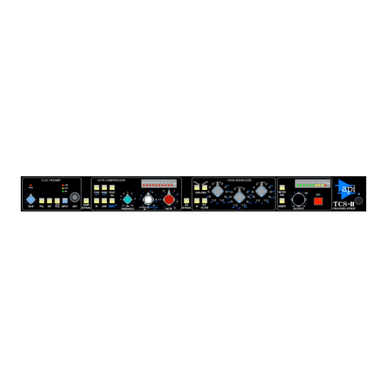
- Page 1 TCS-II The Channel Strip-II 512C – 527A - 550A – 325 Operator’s Manual Written for Automated Processes, Incorporated by Dan Pfeifer Rev. 23-03-19...
-
Page 2: Table Of Contents
Table of Contents About This Manual ..................0 Important Safety Instructions ..............1 1.0 Introduction ..................2 1.1 TCS-II Overview ..................2 2.0 Signal Flow and Block Diagrams ............3 2.1 Default Signal Flow ..................3 2.2 Alternate Signal Flows ................3 2.2.1 Compressor Post Equalizer Signal Flow ............... - Page 3 7.4.2 DC Link ........................ 29 7.5 Rear Panel Signal Flow ................29 8.0 AC Power .................... 30 APPENDIX....................31 A1 TCS-II Technical Specifications ..............32 A2 Block Diagrams ..................34 A2.1 Default Signal Flow ....................34 A2.2 Post EQ Signal Flow ....................34 A2.3 512C Signal Flow ....................
-
Page 4: About This Manual
About This Manual This manual explains the operation and applications of the API TCS-II (The Channel Strip II) signal processor. Incorporating four legendary API signal processors into a stand-alone configuration, the TCS-II provides a flexible, high-quality audio signal chain for most production applications. -
Page 5: Important Safety Instructions
(this may include music) for a period of time. Be safe. WARNING – To reduce the risk of fire or electric shock, do not expose this apparatus to rain or moisture. TCS-II... -
Page 6: Introduction
Compressor gives your track the "in-your-face" punch that has made this circuit an award winner. Also included in the TCS-II is probably the most recognized and revered API EQ of all time, the 550A three- band equalizer with its switchable frequencies and 12dB of boost or cut. The 550A Equalizer's High and Low frequency bands can be individually switched to be shelving EQs, and the "B.P. -
Page 7: Signal Flow And Block Diagrams
2.0 Signal Flow and Block Diagrams 2.1 Default Signal Flow With no routing switches engaged, the default signal flow through the TCS-II is illustrated by the left- to-right order of the unit’s front panel: 512C Preamp -----------> 527A Compressor ------------------> 550A Equalizer--> Insert --> 325 Output The block diagram below illustrates the TCS-II signal flow with no switches engaged except the CUT button. -
Page 8: Compressor Bypass
• Illuminates when engaged The block diagram below illustrates the TCS-II signal flow with the POST EQ switch engaged. No other switches are engaged except the CUT button. NOTE: The order of the First and Second Effect jacks on the rear panel does not change with the compressor when the POST EQ switch is engaged. -
Page 9: Insert
• Illuminates when engaged NOTE: Since the signal can be externalized at multiple points in the audio path, the TCS-II does not have a dedicated “insert send” output. PRE OUT, FIRST EFFECT OUT, and SECOND EFFECT OUT are intended to be used as “insert sends” as needed. -
Page 10: 325 Output Section Signal Flow
II with only the CUT switch engaged. 2.5 Rear Panel Signal Flow The TCS-II signal flow is illustrated by the right-to-left order of the unit’s rear panel. The order of these interfaces remains constant, regardless of the order of the 527A Compressor and 550A Equalizer in the signal path. - Page 11 The input is instead fed with the signal present on the inserted plug. The INSERT RETURN is only active when the INSERT switch on the front panel is engaged. TCS-II...
-
Page 12: Input Section: 512C Preamplifier
3.0 Input Section: 512C Preamplifier The input section is equipped with the legendary API 512C Preamplifier with microphone, instrument, and line inputs. The 512C Preamplifier is designed to provide an unusually good sounding front-end for all types of audio recording applications. -
Page 13: 512C Input Selection
IMPORTANT: Caution should be exercised when engaging phantom power! Damage can occur if phantom power is applied to some audio devices, including most ribbon microphones. The TCS-II output should also be muted (CUT) when engaging the 48V switch. -20dB PAD: Inserts a -20dB attenuator after the MIC input •... -
Page 14: Instrument Input
3.4 512C Polarity Inverter A polarity inverter (sometimes referred to as a “phase reverse”) is available at the output of the 512C Preamp. POL (Polarity): Inverts the polarity of the signal at the output of the preamp • Illuminates when engaged TCS-II... -
Page 15: 512C Level Indication
Plugging into the PRE OUT jack does not break the connection to the FIRST EFFECT IN jack 3.7 512C Preamp Block Diagram The block diagram below illustrates signal flow through the 512C Preamp section of the TCS-II with no switches engaged. TCS-II... -
Page 16: Dynamic Processing: 527A Compressor
527A. 4.1 527A Compressor Overview and Features The 527A Compressor is equipped with functions common to other of compressors in the API line like "feed-forward" (NEW) and "feed-back" (OLD) gain reduction methods selectable on the front panel, provide a choice of "that old type", or "the new type"... -
Page 17: 527A Compressor Controls
SOFT response curve characteristic at the onset of compression THRUST • ® : Inserts the patented API high-pass filter before the RMS detector • LINK: Activates the DC LINK for stereo/multichannel processing with other TCS units • COMP BYPASS (Compressor Bypass): Activates the 527A hard bypass in the audio path •... -
Page 18: Ratio
In a feed-back compressor, the RMS detector gets its signal from the output of the gain reduction device (VCA). This is how older API 525, 1176 type, and 660 type compressors work. This yields a smoother, softer, more transparent sound. -
Page 19: Compression Knee
HARD: Sharper, more aggressive response curve (switch engaged) • Illuminates when engaged Soft Knee Compression SOFT: Rounded, more graduate response curve • Gradual onset of compression (fade-in up to the set ratio) • Similar to an “over-easy” type knee • More transparent TCS-II... -
Page 20: Thrust
The patented ® circuit has been used for many years in the famed API 2500 Stereo Compressor, ATI Paragon and Paragon II consoles, as well as the Pro-6 Input Strip. This circuit places a filter in front of the RMS detector with a slope of 10dB per decade (-3dB/8va), which is the inverse of the pink noise energy curve. -
Page 21: 527A Compressor Routing
When the COMP BYPASS switch is engaged, the 527A Compressor is completely removed from the audio path via a hard relay-based bypass. COMP BYPASS (Compressor Bypass): Engages the 527A Compressor hard bypass in the audio path • Relay hard bypass • Illuminates when engaged TCS-II... -
Page 22: Compressor In Switch
4.3.4 Compressor IN Switch To emulate the API 500 Series version of the 527A, the compressor in the TCS-II is equipped with an internal IN/out switch. The IN switch must be engaged for compression to have effect. IN: Activates the 527A Compressor •... -
Page 23: Spectral Processing: 550A Equalizer
Still copied but never duplicated, the 550A Equalizer became API's standard channel module EQ when the company began manufacturing consoles in 1971. With virtually all existing units spoken for, popular demand for this EQ resulted in API finally resuming production in 2004. -
Page 24: 550A Equalizer Controls
+/- 2dB, 4dB, 6dB, 9dB, 12dB • Switchable shelving Low Frequency SHELVING: Changes the low frequency band from a peaking EQ to a shelving EQ • All frequencies below the selected center frequency will be boost or cut • Illuminates when engaged TCS-II... -
Page 25: Mid Frequency Band
512C Preamp will feed the 527A Compressor via FIRST EFFECT jacks • 527A Compressor will interface via the FIRST EFFECT jacks on the rear panel • 550A Equalizer will interface via the SECOND EFFECT jacks on the rear panel TCS-II... -
Page 26: Equalizer Pre Compressor
Illuminates when engaged 5.3.4 Equalizer IN Switch To emulate the API 500 Series version of the 550A, the equalizer in the TCS-II is equipped with an internal IN/out switch. When the engaged, the equalizer is in the audio path. IN: Activates the 550A Equalizer •... -
Page 27: Output Section: 325 Line-Driver
API 325 Line-Driver output circuit (a 2520 and 1:3 output transformer) taken directly from API console designs. The 10-segment LED level meter can be switched to monitor the output level of the TCS-II or the output of the 512C Preamp. Features: •... -
Page 28: Output
• ¼” tip-ring-sleeve jack NOTE: Since the signal can be externalized at multiple points in the audio path, the TCS-II does not have a dedicated “insert send” output. PRE OUT, FIRST EFFECT OUT, and SECOND EFFECT OUT are intended to be used as “insert sends” as needed. -
Page 29: 325 Output Section Routing
INSERT RETURN jack on the rear panel by engaging the INSERT switch. 6.3 325 Output Section Block Diagram The block diagram below illustrates signal flow through the 325 Line-Driver output section of the TCS- II with only the CUT switch engaged. TCS-II... -
Page 30: Rear Panel Interface
7.0 Rear Panel Interface The rear panel of the TCS-II provides a comprehensive package of interfacing options. With the exception of the microphone and instrument inputs, all audio inputs and outputs are balanced, low-impedance, +4dBu line-level connections. All ¼” connectors are tip-ring-sleeve phone jacks. -
Page 31: Audio Path Outputs
Illuminates when engaged 7.2 Audio Path Outputs The TCS-II provides multiple audio outputs at various points in the audio path. All ¼” outputs are non- switching jacks so inserting a plug will not break the connection with the input it feeds. -
Page 32: Audio Path Half-Normals
CHANNEL OUT: Main TCS-II audio output • Fed from the 325 Line-Driver • Male, 3-pin XLR • +4dBu line-level • Balanced • Low-impedance 7.3 Audio Path Half-Normals There are two “half-normalled” connections on the rear panel. Switching jacks are used on the FIRST EFFECT IN and SECOND EFFECT IN, so the signal fed from the normal will be broken when a plug is inserted. -
Page 33: 527A Compressor Side Chain & Dc Link Connections
Illuminates when engaged 7.5 Rear Panel Signal Flow The TCS-II signal flow is illustrated by the right-to-left order of the unit’s rear panel. This order of these interfaces remains constant, regardless of the order of the 527A Compressor and 550A Equalizer in the signal path. -
Page 34: Ac Power
The fuse holder is located on the rear panel. • 0.5A/0.25A 250V The AC power switch for the TCS-II is located at the lower right of the API logo on the front panel. • A blue LED indicator illuminates when the unit is on. -
Page 35: Appendix
APPENDIX A1 TCS-II Technical Specifications A2 TCS-II Block Diagrams A3 TCS-II Setup Sheet A4 API Limited Warranty and Service TCS-II... -
Page 36: A1 Tcs-Ii Technical Specifications
A1 TCS-II Technical Specifications i. 512C Preamplifier Specifications Rear Connector: XLR MIC Input Balanced ¼” TRS LINE Input Front Connector: HI-Z ¼” Unbalanced Instrument Input (INST) Gain Range: MIC: 14dB min. 68dB max. INST: 14dB min. 50dB max. Maximum Input Levels:... - Page 37 Cabling Depth From Mounting Surface: 13.5” Weight: 10lb 10oz Size: 19x11.5x1.7”, L x W x H Shipping Weight: 14lb 9oz Shipping Size: 23.25x16x6.5”, L x W x H API reserves the right to update or modify any specification listed herein. TCS-II...
-
Page 38: A2 Block Diagrams
A2 Block Diagrams A2.1 Default Signal Flow The block diagram below illustrates the TCS-II signal flow with no switches engaged except the CUT button. This is the “default” signal flow through the unit. A2.2 Post EQ Signal Flow The block diagram below illustrates the TCS-II signal flow with the POST EQ switch engaged. No other switches are engaged except the CUT button. -
Page 39: A2.3 512C Signal Flow
A2.3 512C Signal Flow The block diagram below illustrates signal flow through the 512C Preamp section of the TCS-II with the MIC IN selected as the active input and no switches engaged. A2.4 325 Output Section Signal Flow The block diagram below illustrates default signal flow through the 325 Line-Driver output section of the TCS-II with only the CUT switch engaged. -
Page 40: A3 Tcs-Ii Setup Sheet
A3 TCS-II Setup Sheet TCS-II... -
Page 41: A4 Api Limited Warranty And Service
API. Accordingly service or modification of any API unit except by an authorized API representative may VOID this warranty. API reserves the right to inspect any products that may be the subject of any warranty claims before repair or replacement is carried out. Final determination of warranty coverage lies solely with API. - Page 42 8301 Patuxent Range Road Jessup, MD 20794 USA 301-776-7879 http://www.apiaudio.com...
Need help?
Do you have a question about the TCS-II and is the answer not in the manual?
Questions and answers